
In this post, I’ll provide a step-by-step guide to building an inexpensive Solar Scintillation Seeing Monitor. The SSSM is a handy device which monitors the atmospheric seeing conditions during solar imaging. This SSSM can be built for a fraction of the cost of commercially available devices. You can use the SSSM to monitor seeing conditions through the day, or even to control your camera to capture images during the best seeing conditions.
Background
The original design for the SSSM was published by E. J. Seykora at the Department of Physics, East Carolina University, as described here: https://www.ecu.edu/cs-cas/physics/upload/An-Inexpensive-Solar-Scintillation-Seeing-Monitor-Circuit-with-Arduino-Interface-final2.pdf
The design of the device was further refined by Joachim Stehle, who included a modification to make calibration of the SSSM easier and suggested alternative components where the originals have proved hard to find. Joachim has also developed and released a free plug-in for the (also free) FireCapture software enabling solar image capture to be triggered by favourable seeing conditions, available here: http://www.joachim-stehle.de/sssm_eng.html
There are also a couple of useful discussion threads about this project on the SolarChat forum here: https://solarchatforum.com/viewtopic.php?t=16746 and here: https://solarchatforum.com/viewtopic.php?f=4&t=21002
In the build presented here, I have added support for an inexpensive OLED display, thus allowing the SSSM to be used independently of a PC or laptop. I have also re-factored the Arduino sketch to make it more modular and readable. The current sketch is available on GitHub and I’d encourage you to contribute any further improvements here: https://github.com/IanLauwerys/SSM
How does the SSSM Work?
The SSSM uses a silicon photo-diode to measure the intensity of sunlight falling on it. Scintillation (fluctuations in intensity) during each half-second sample makes it possible to estimate the relative quality of the seeing. As daytime seeing is dominated by air turbulence close to the ground, the photo-diode must be mounted close to the aperture of your solar telescope.
The SSSM consists of five main components:
- A silicon photo-diode which measures solar intensity.
- A simple amplifier circuit to convert the tiny current generated by the photo diode in to measurable voltages.
- An Arduino board to convert the voltages into data.
- A laptop or PC which records the results (sent via USB) and controls the image capture software.
- Optionally, an OLED display module and battery may be used to operate the SSSM independently of a PC.
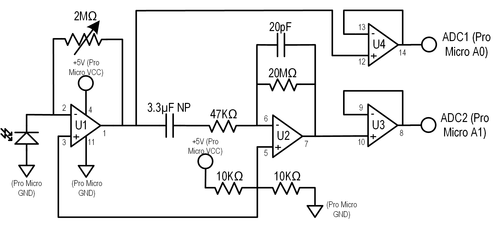
The SSSM circuit diagram is reproduced below (based on Joachim Stehle’s modified design). Don’t worry if you’re not an electronics expert as I’ll provide you with a painting by numbers guide to parts and assembly later. All you really need to know is that sunlight hits the photo-diode at the left of the diagram, and a couple of voltages come out of the connections at the right. These are then measured by an off-the-shelf micro-controller board and results sent to your computer. Easy(!)
Building the SSSM
This project will require basic soldering skills; mine probably wouldn’t scrape ‘average’ to be honest. Some previous experience with Arduino micro-controller boards would also be useful, but all you need to do is change a few numbers here and there so don’t panic if you’re new to them. Most importantly of all a patient, methodical approach will get you over any minor obstacles.
Equipment List
You will need the following equipment:
- A soldering iron with a fine tip and solder.
- A ‘helping hands’ tool to hold your work when soldering.
- A multi-meter for checking your soldering is OK.
- A de-soldering pump and de-soldering braid for when you find your soldering isn’t OK!
- A small drill bit for metal.
- A fine saw or a rotary tool and cutting discs (i.e. a Dremel or equivalent).
- A sharp craft knife.
- A hot-glue gun and hot-glue (useful but not essential).
- A prototyping breadboard and set of link wires (useful but not essential).
- An illuminated magnifier (useful if your eyesight is as bad as mine).
- A laptop or PC for programming the Pro Micro board – your imaging laptop will be fine provided it has a USB port!
- A USB cable, type ‘A’ to micro-USB (i.e. the standard PC/Laptop connector to the small connector found on most current smartphones). Make sure the cable is long enough to reach from your laptop to wherever you plan to mount the SSSM on your solar telescope!
Parts List
You will need the following parts from an electronics retailer or eBay:
- 1 x ATmega32U4 Pro Micro Board. Important: You will require the 5 volt 16MHz variant, not the 3.3 volt 8MHz version. Note: This board is often referred to as often referred to by sellers as a ‘Leonardo Pro Micro’, but it is not the same thing as the official Arduino Leonardo board which has a different layout.
- The Pro Micro clones suggested here have the advantage of being very small, providing on board USB connectivity and being incredibly cheap (3 to 5 pounds/dollars per unit).
- There are many other Arduino compatible boards available, and it is entirely possible adapt this project to use one of them if you are comfortable doing so. The key requirements are to provide a clean 5V supply to the amplifier circuit and to have on-board USB support if you wish to hook up to a computer.
- 2 x Arduino Headers, 2.54mm pitch, 12 pin. These are plastic strips with connector pins that need to be soldered to the Pro Micro board. You can purchase boards with the headers already attached or kits that include both the board and the headers.
- 2 x Arduino Header Sockets, 2.54mm pitch, 12 pin. These are the corresponding sockets that the headers plug in to. Again they may come as part of a kit. You can solder the header pins directly to the strip-board without headers if you wish, but it’s easier all round to use sockets.
- 1 x LMC6484 Quad Rail-to-Rail Op Amp. This is a small integrated circuit (chip).
- 1 x IC DIP Socket, 2.54mm pitch, 14 way (two rows of 7 pins) to hold the LMC6484.
- 1 x 2KΩ Multi-turn Variable Resistor. Also known as a ‘Potentiometer’, ‘Trim Pot’ or ‘Rheostat’. Try to get a multi-turn type as these have much finer adjustment than the single turn type.
- 1 x 10KΩ Resistor, 1 x 47KΩ Resistor. In the long run you’ll probably find it cheaper to buy packs of assorted resistors rather than paying postage and packing on small quantities for each project.
- 1 x 20MΩ resistor. Larger value resistors like this tend to be sold singularly or in small quantities.
- 1 x 3.3µF NP Capacitor. Important: NP stands for ‘Non-Polar’. Typically electrolytic capacitors have a polarity, i.e. they must be connected properly with respect to positive/negative in the circuit. Since this capacitor has to handle (low voltage) AC current it must be the non-polar type (also known and ‘Bipolar’) and not a standard electrolytic capacitor.
- 1 x 20pF Capacitor. Most likely to be a ceramic disc capacitor, and again these tend to be sold in multi-packs and assortments.
- 1 x Photo-diode, either VTP4085H or BPW34. The VTP4085H is quite hard to get hold of and pretty expensive. The BPW34 is much easier to obtain for a few pounds or dollars on eBay and works just as well. Important: Some BPW34 ‘s are infra-red (IR) filtered; you should opt for the non-filtered type.
- 1 x Veroboard / Strip-board, 2.54mm pitch, minimum 25 x 16 holes. If your soldering skills are rusty, you may want a larger piece of strip-board so that you can space the components out more. You’ll also find it useful to have a small pieces of strip-board to mount the Photo-diode and its connecting wires, plus the optional OLED display and it’s connecting wires.
- Bridge / Connector Wire: You’ll need a quantity of fine, insulated wire to make up bridge wires for the strip-board circuit and also for connections to the Photo-diode and the optional OLED Display board. Braided wire is more flexible and far less prone to break off at connection points, but solid wire is much easier to insert into the strip-board through-holes.
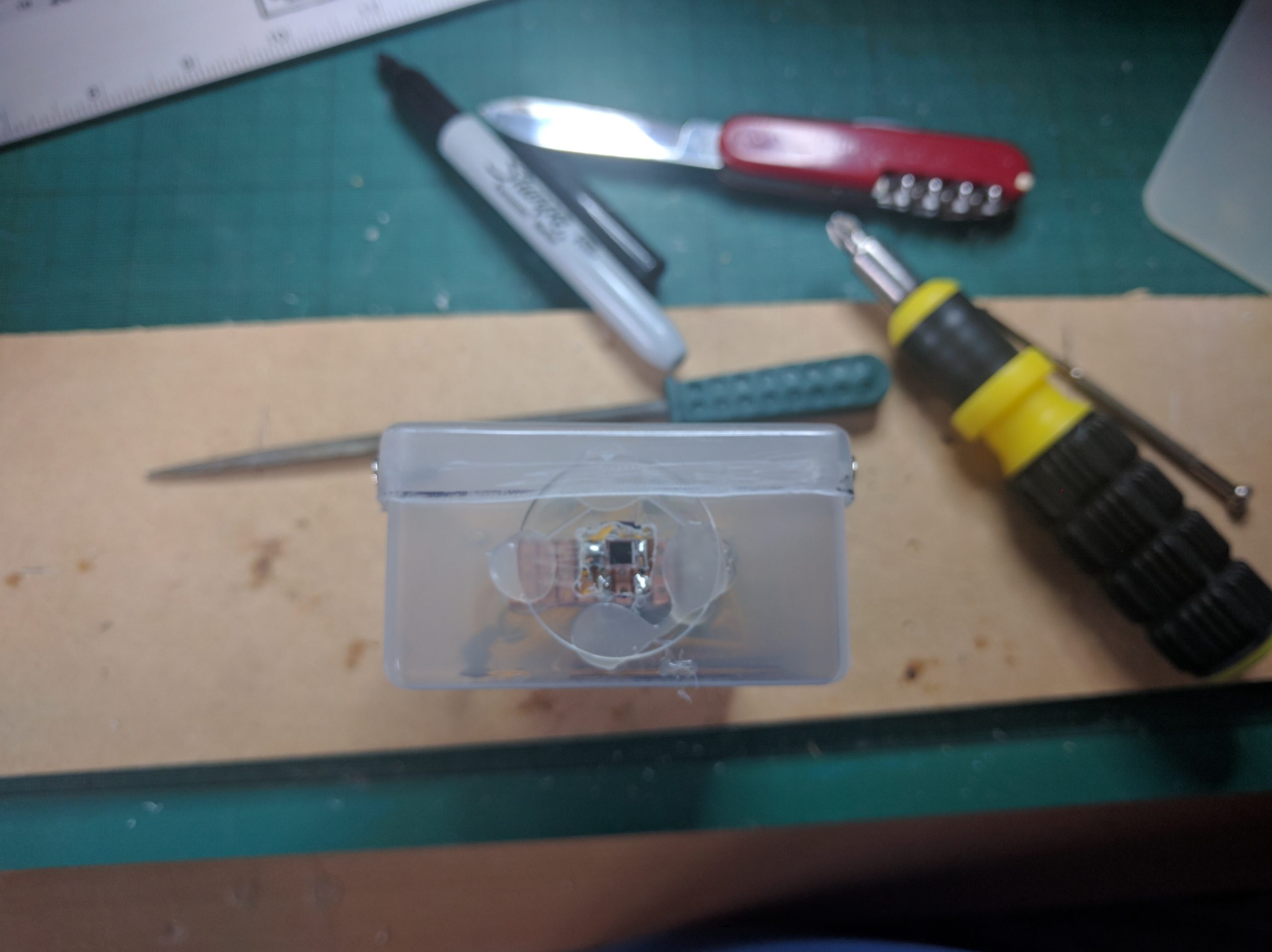
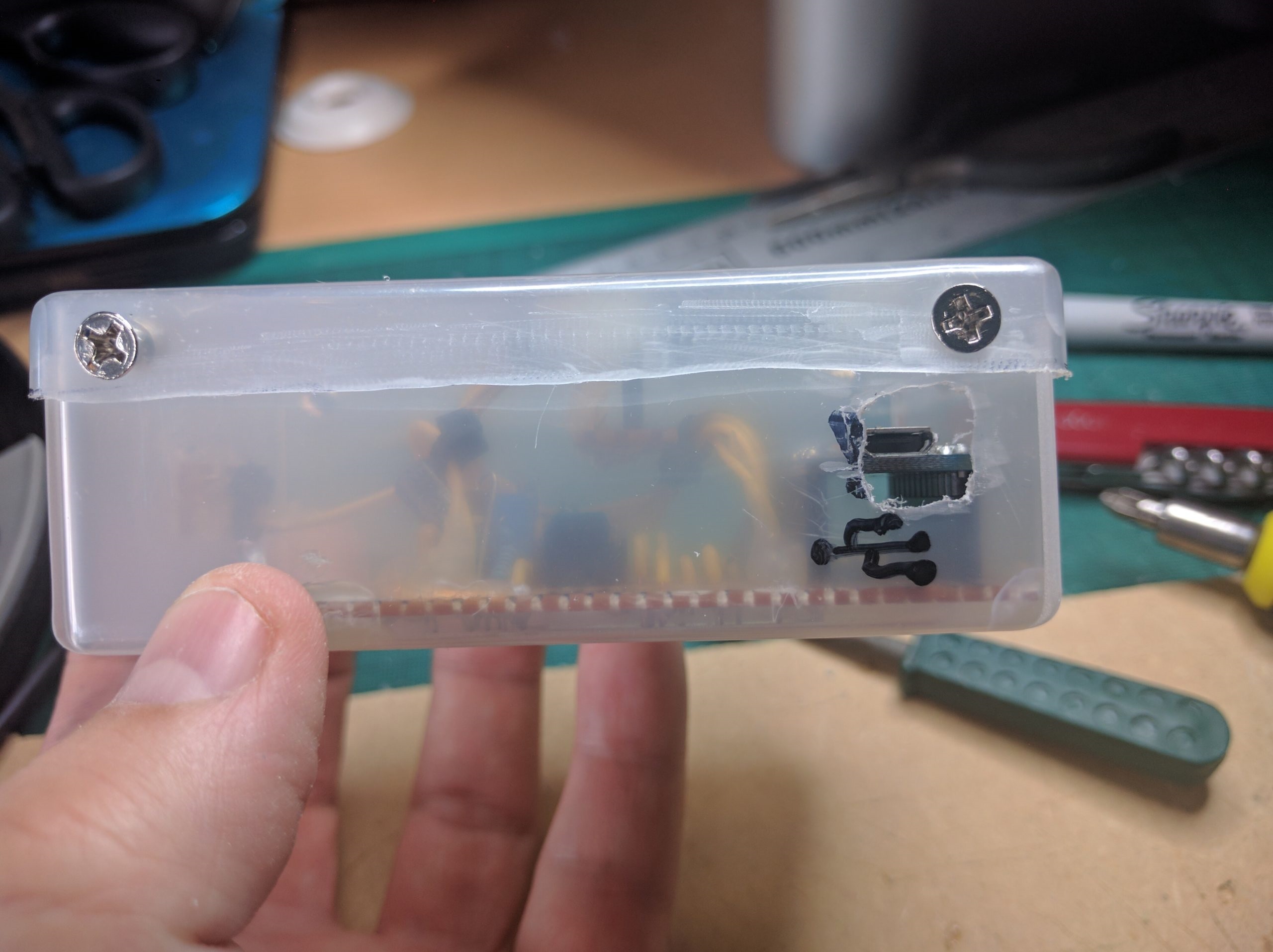
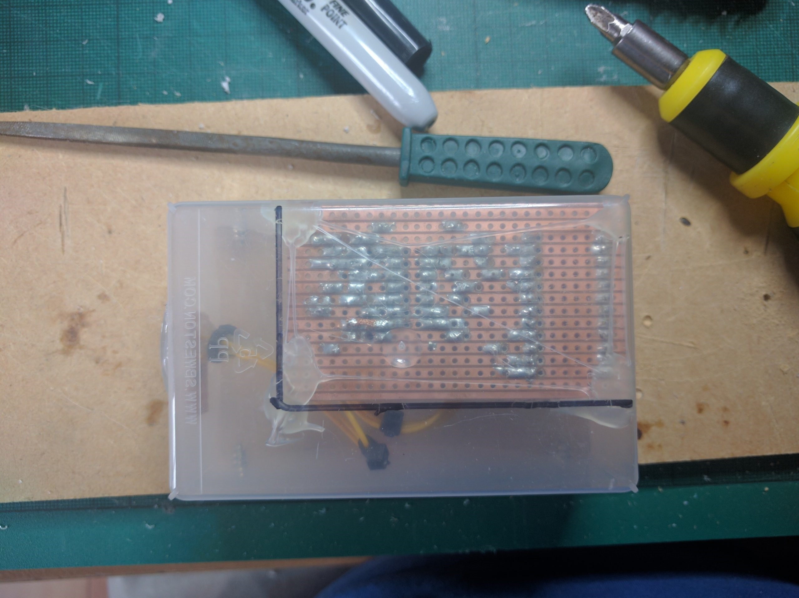
- Project Box: You’ll need a small project box to house the complete circuit. It will need a hole to access the Pro Micro’s USB socket, a small hole to access the variable resistor’s adjustment screw and a hole or window for the photo-diode to see through. I modified an old plastic business card box for my project – it’s a bit rough and ready but does the job.
- 1 x Arduino Compatible OLED display Board (optional). Again these are readily available from on-line electronics retailers and eBay. The minimum supported display size is 96 x 16 pixels, and other common sizes are 128 x 32 and 128 x 64 pixels.
- The main challenge is that there are so many different modules available. If you buy from one of the larger on-line electronics retailers, you’ll probably get clear documentation describing the pin-outs of the unit and how to use it.
- If you buy from eBay, prices are lower but there are lots of different units, they’re not very well described by sellers, there is little or no documentation available and in some cases the pin-outs printed on the device are plain wrong. You may find yourself having to experiment a bit as I did. If you’re not comfortable doing so, remember that the basic SSSM will work fine without a display.
Step-by-Step Build Guide
Step 1: Test the Pro Micro
The first step is to ensure your Pro Micro board works out of the factory in case you need an exchange or refund. Download and install the Arduino IDE (Integrated Development Environment) here: https://www.arduino.cc/en/Main/Software
There are IDE versions available for Windows, Mac and Linux, and even an on-line web-based version (though I have not tried it myself). You will also need install the Pro Micro drivers and set up the board in the Arduino IDE. The steps are different for each operating system, so I’ll point you at two great guides.
Windows: https://learn.sparkfun.com/tutorials/pro-micro–fio-v3-hookup-guide/installing-windows
Mac and Linux: https://learn.sparkfun.com/tutorials/pro-micro–fio-v3-hookup-guide/installing-windows
Remember to take anti-static precautions before handling the Pro Micro. Touching a bare metal radiator pipe from time to time will discharge any static that you have accumulated.
Finally test the Pro Micro by opening one of the example sketches (Arduino programs) and uploading it, e.g. the ‘Blink’ sketch. Remember to select the correct board type from the Tools -> Board menu (the ‘Sparkfun Pro Micro 5V /16MHz’).
If you run in to problems, check this troubleshooting guide: https://learn.sparkfun.com/tutorials/pro-micro–fio-v3-hookup-guide/troubleshooting-and-faq
Step 2: Assemble the Pro Micro
If the Pro Micro board was supplied without header pins attached, you’l need to attach them. The easiest way to do this is to plug the header sockets in to your breadboard, insert the long side of the header pins in to the sockets and then slide the holes in the Pro Micro Board on to the short side of the header pins.
If you don’t have a breadboard, you can slide the header pins through your strip-board and then in to some hard foam (e.g. polystyrene packaging material). The object is to ensure that the strip-board, headers, header pins and Pro Micro board are aligned squarely before you start soldering. If you solder the header pins to the board by eye, they could end up at an angle and you won’t be able to plug them in to the sockets later.
Assuming you have everything lined up correctly, you should have two rows of short pins sticking up just proud of the top side of the Pro Micro. Now work along with your soldering iron and solder fixing each pin to the metal contact ring on the upper side of the board. Try not to overheat the board by applying the iron for too long, and check you have a nice shiny solder contact when it cools; if it is dull and grey it may not have made good contact so check again. Avoid bridging solder between adjacent contacts, and use your de-soldering tools to clean up if you do.
Step 3: Mark Out and Prepare the Strip-board
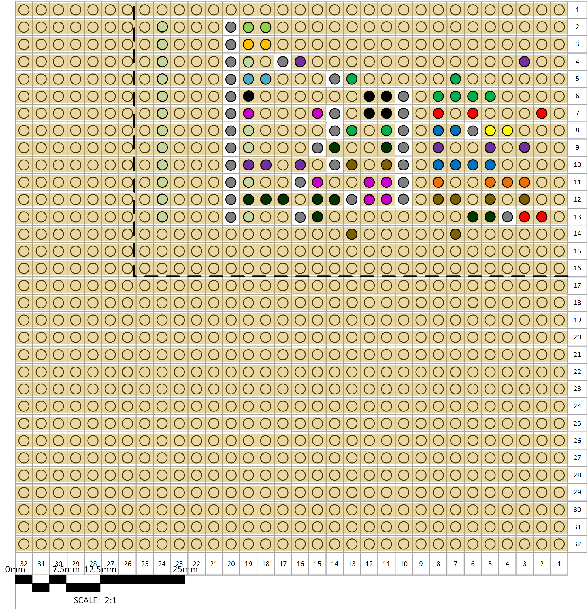
The next step is to mark out and prepare the strip-board. You’ll notice that it has two sides; a plain ‘top’ side and a shiny ‘bottom’ side. In our layout, the copper strips run horizontally across the board, not from top to bottom – this is important so get it right! The diagram below shows the locations of the components and linking wires on the top side of the board. Note that the optional OLED display module at the right-hand side is attached by loose connecting wires and isn’t fixed to the main strip-board. Typically D1, the photo-diode, would also be mounted on another separate piece of strip-board and hooked up to the main board with connector wires.
As shown by the black dotted line, you will need a piece of strip-board that is at least 16 copper strips tall and 25 holes wide for the main circuit board. Count out the strips and holes and mark top and the bottom of the board using a marker pen or scribe. Double-check your markings and make sure they are aligned on both sides of the board, and double-check you have the right number of rows and columns.
Now cut the strip-board to size using a fine saw or a rotary tool (Dremel) and cutting disk. I have left a spare row of holes next to the cuts so you don’t have to be too precise. Fixing the strip-board to a piece of scrap wood using spring clamps or even Duck tape will make it easier to cut neatly. The process produces a lot of dust so wear a dust mask, plus suitable eye protection if using a rotary tool.

To help you with the next step, you may want to insert the IC DIP Socket and the two Arduino header sockets in the appropriate positions on the board. Mark out where they appear on the underside of the strip-board and then remove them again.
Now flip over the board and begin working on the bottom (copper side). You can see from the diagram below that I’ve flipped the board horizontally so that column 1 moves from the left side to the right side. You will need to cut the tracks in the places shown on the diagram by the grey spots on a white background. There are two main sets of cuts, between the pair of Pro Micro headers (12 strips cut in column 20) and between the IC DIP Socket (seven strips cut in column 10), plus 11 other individual cuts, making for a total of 30 cuts.
The easiest way to cut the tracks is to use a sharp metal drill bit with a diameter that is the width of a single track (but no wider to avoid cutting adjacent tracks). Hold the drill-bit between your fingers (or use a pin-vice if you have one) and insert it centrally in to a hole where you want to make a cut. Now turn the bit clockwise whilst applying gentle pressure on the board. The drill bit should start to scrape off the copper track and will also start enlarging the hole. Keep going until you have completely cut the track – this should happen well before you’ve drilled through the board. Check with your multi-meter in resistance mode that there is no connection from the strip on one side of the cut to the other.
Don’t use the drill bit in an electric drill or rotary tool, as you’ll likely damage the board or cut extra tracks if you slip. Nor do I recommend using a craft knife or other bladed tool to make cuts, as it is very easy to slip and damage adjacent tracks. There are purpose-made strip-board cutting tools available which are basically a drill-bit with a plastic handle, but you’ve probably got a suitable drill bit already.
Step 4: Solder the Header Sockets and IC Socket
Now insert the 12 pin header sockets in to the top side of the strip-board columns 19 and 24). Use a piece of Duck tape to hold them in place, ensuring they are sat squarely on the board. Flip over and solder each of the pins to the copper strips in turn. As before, work methodically and ensure you have a nice shiny solder contact without excess solder or any solder bridges between pins or strips.
If you apply too much heat to the copper strip, it will become detached from the board. If you’re lucky you may be able to repair the damage by creating a bridge using fine wire or copper de-soldering braid. If you’re unlucky you will be faced with starting over again (and de-soldering everything from the damaged strip-board). Proceed slowly and allow the board to cool between each soldering operation.
Next, insert and solder the IC socket (columns 8 and 11). The socket will probably have a semi-circular or ‘D’ shaped mark at one end, either printed on or embossed in the plastic. Make sure the D is at the top of the stripboard as this will help you to orient the IC correctly later.
Don’t insert the IC or the Pro Micro board at this stage, though do check the header sockets and pins on the latter line up before proceeding. Both devices are susceptible to electrostatic discharge (ESD) and since we’ll be handling the board a lot it is better to leave them in their ESD-safe packaging for the time being.
Step 5: Make and Solder the Bridge Wires
Refer to the strip-board diagram (top view) above. You will see 13 bridge wires depicted by lines of different colours and lengths running from top to bottom of the strip board. (Ignore the lines at angles on the right of the board, these are link wires that fly off the board to the optional OLED display module which we will cover later). The colours of the wires just show which parts of the layout are connected, e.g. all the purple solder points and purple lines are one common connection.
Make a bridge wire by stripping a short amount of insulation from one end of your fine wire so that it will pass through a hole and allow you to solder it to the copper strip underneath. Now bend the cut end at 90 degrees so that the link wire sits flat on the board. Figure out where you need to cut the wire, leaving enough extra to strip, push through the other hole and solder.
Use your multi-meter to check your connections are good and that you haven’t accidentally bridged tracks with solder. Refer to the layout diagram colours to work out what should or should not be connected. Bear in mind that once you start to add components in the remaining steps below, you will get connectivity between different parts of the layout!
Step 6: Solder the Resistors
Again refer to the strip-board diagram (top view) above along with the table of component numbers. Solder the resistors in the appropriate locations. Where the spacing of the strip-board holes is narrow, you will have to solder the resister vertically; insert one lead in the hole and bend the other lead through 180 degrees so it ends up adjacent to the first lead, taking care not to snap it. The orientation of the resistors doesn’t matter as they don’t have polarity.
I use my multi-meter to check the resistor values , or you can use the color bands printed on them as explained here: https://en.wikipedia.org/wiki/Electronic_color_code#Resistor_color-coding
The variable resistor (potentiometer) will most likely have three pins or tabs, and typically you will need to connect the center pin and one of the outside pins; either is fine but make sure to leave the other outside pin unconnected by cutting it off. You can check using a multi-meter across the two pins you plan to use; the resistance should change as you turn the adjustment screw.
Step 7: Solder the Capacitors
A bit more care is needed with the capacitors. C1 must be a non-polar capacitor, and like the resistors can be soldered in either orientation. C2 is likely to be a ceramic disc capacitor and again it can be soldered in either orientation.
In the very unlikely event that C2 is an electrolytic capacitor, the the negative lead must be attached to the track adjacent to pin 6 of the Pro-Micro board and the positive lead to the track adjacent to pin 7.
Step 8: Attach the Photo-diode
The photo-diode is very small and usually has equally short connector leads. To make assembly easier, cut a small piece of strip-board, perhaps eight tracks wide by four holes high. Attach the photo-diode leads to two of the copper tracks at one side of the board, with a gap of one track between the diode leads.
The photo-diode leads probably won’t fit through the strip-board holes. Instead, solder them to the surface of the track on the copper side of the board, taking care not to bridge between tracks.
Next make up two fly-leads from thin connector wire and solder through holes on the tracks to which the photo-diode is connected. The fly leads need to be reasonably long so that the photo-diode can be mounted on the front of the project box later. You may also want to strengthen the joints by using some hot-glue at the points where the fly leads attach to the photo-diode board and the main circuit board.
Finally, solder the two fly leads to the strip board as shown in the diagram above at D1. The unused part of the small stripboard can be used to handle the photo-diode more easily and later to mount it in position with hot glue.
The photo-diode has polarity; the cathode (negative) lead has a small metal tag sticking out just where it exits the diode body. The anode (positive) lead has no tag and should be connected to pin 2 of the Pro-Micro (the red connection on the left side of layout diagram).
Step 9: Insert the IC
After taking anti-static precautions, insert the LMC6484 IC in to the IC socket in the correct orientation. Pin 1 should be at the top-left of the circuit board – there will be a small D-shaped mark embossed in to the IC body or printed on to it which should be at the top of the layout diagram.
Unless you have an IC insertion tool, it can be a bit tricky to get all of the IC legs in to the socket as they are angled slightly outwards (to act as a spring and hold the IC in the socket). It may help to bend the pins on one side inwards slightly by pressing them edge-wise on a flat surface. Flip the IC over and do the same to the other set of pins. Take care as repeated bending will cause the pins to weaken and snap off!
Step 10: Insert the Pro-Micro
Even if you plan to add the optional OLED display, now is a good time to test the basic functionality of the SSM. After taking anti-static precautions, insert the Pro-Micro board in to the header sockets. The USB socket should be at the bottom of the board as per the layout diagram.
Step 11: Test the Pro-Micro
Connect the Pro-Micro to your PC or laptop using a USB cable; it should power up and the LEDs illuminate as they did when we first tested the board. The “Blink” sketch may make the LEDs flash if that was the last thing you loaded to the board when testing in Step 1.
If the board doesn’t appear to be working, disconnect the USB cable, remove the Pro-Micro from the header sockets and re-connect it to the PC via USB. If the board works OK when it isn’t plugged in the the SSSM circuit, then you’ll need to double check your layout, soldering, etc. for any shorts or other errors. If the board doesn’t work in isolation, then try the troubleshooting guide linked in Step 1.

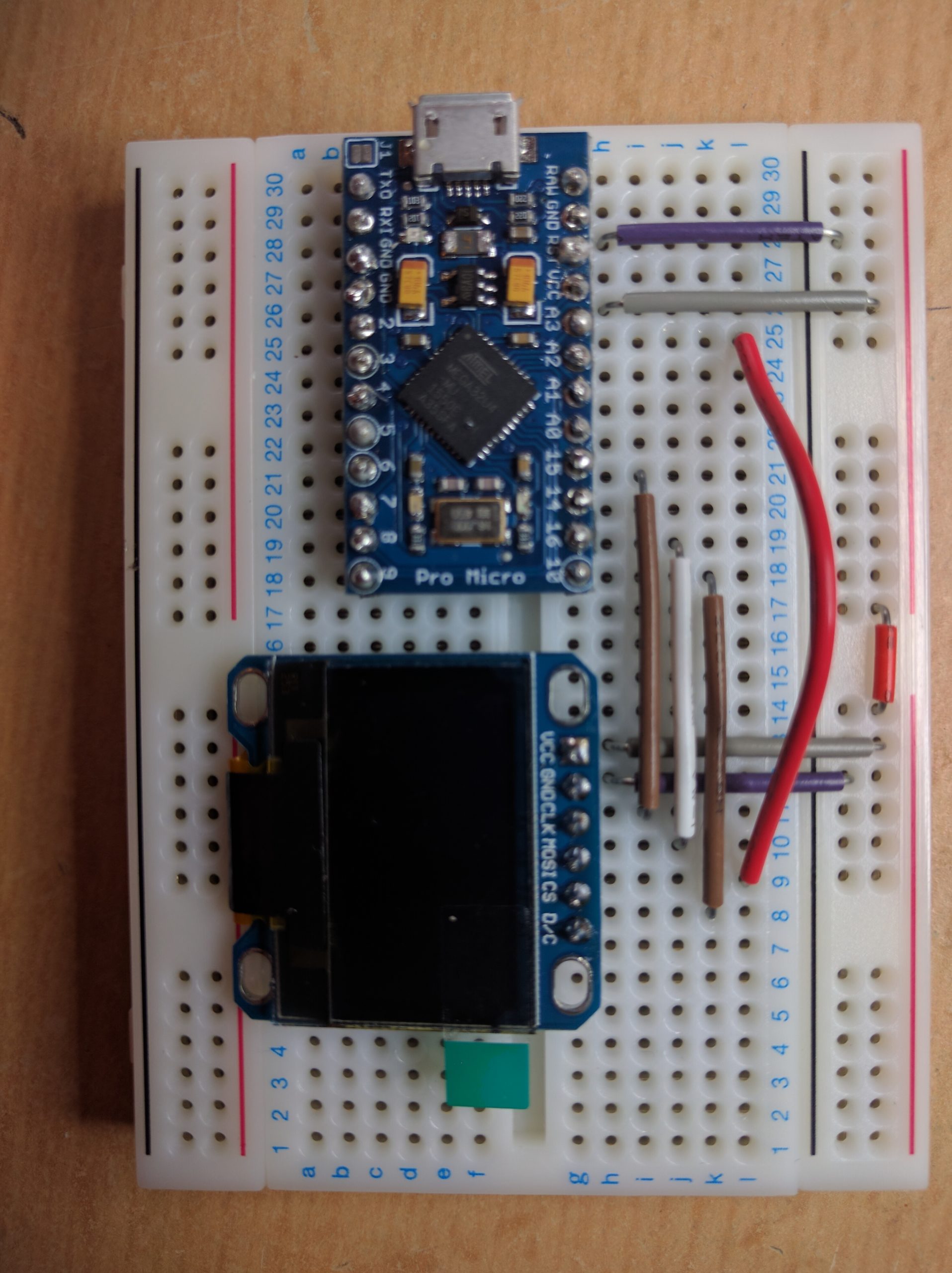
Assembled SSSM including OLED display
Step 12: Get the SSSM Sketch
Open the Arduino IDE and create a new sketch (File -> New). Copy the entire code for the SSSM sketch from this web page: https://github.com/IanLauwerys/SSM/blob/master/SSM_Sketch/SSM_Sketch.ino
Paste the sketch in to the Arduino IDE and save the sketch file (File -> Save), calling it something useful like SSSM_Sketch. Now check that the code is correct using Sketch -> Verify/Compile. After a few seconds the console at the bottom of the IDE should display something like:
Sketch uses 6,388 bytes (22%) of program storage space. Maximum is 28,672 bytes.
Global variables use 194 bytes (7%) of dynamic memory, leaving 2,366 bytes for local variables. Maximum is 2,560 bytes.
The exact storage usage will vary depending on which options are enabled in the sketch. If you get an error message of some sort, then check you have correctly pasted the code from the original (try File -> Preferences -> Display Line Numbers; there should be exactly 393 lines of code in the IDE window).

Step 13: Upload and Test the SSSM Sketch
Make sure the Pro Micro is connected to the PC and selected in the IDE as the active board (as described in Step 1) and upload the SSSM sketch (Sketch -> Upload). After a few moments the Pro Micro will restart and run the SSSM sketch.
Open the Serial Monitor in the IDE (Tools -> Serial Monitor). If the SSSM is working correctly, you should see an ongoing series of lines being printed in the monitor window as follows:
A0: 0.00
A1: 0.00
A0: 0.00
A1: 0.00
:
etc.
“A0” is the intensity reading (how bright the Sun is) and “A1” is the variation reading (the quality of the seeing based on how much the intensity varies over the course of each reading). At this point you’re likely to get values of zero for both since you’re sat indoors at your computer!
Step 14: Calibrate the SSSM
Next you’ll need to calibrate the SSSM by exposing it to sunlight so take your SSSM and laptop outdoors, or move over to an open window.
It is important to perform the calibration using full sunlight. Whilst you may be able to test the SSSM using a (really) bright lamp held next to the photo-diode, or outside during hazy conditions, you won’t get useful results as only full sunlight will generate enough current for the circuit to work properly.
Aim the photo-diode directly at the Sun and check the readings on the Arduino IDE Serial monitor. The first number you should focus on is the value of A0. The number represents the voltage from the first stage of the SSM circuit. We want the value to be somewhere between 0.5 and 1.0 volts in full sunlight, ideally as close to 1.0 as possible.
The voltage can be adjusted using the variable resistor (R1). Use a small screwdriver to turn the adjustment screw on the variable resistor whilst monitoring the value of A0 on the serial monitor. If you’re using a multi-turn resistor as recommended, you’ll probably find that you have to turn the adjustment screw many times before anything changes, and then you’ll overshoot in a fraction of a turn. Keep tweaking it patiently until you get as close as you can to 1.0 (volts) in full sunlight.
Once you have calibrated A0 to read as close to 1.0 as you can, you shouldn’t need to adjust it again. Now look at the values being displayed for A1. Ideally these will be anywhere between 0.00 and 10.00 depending on the seeing conditions. If the values are outside this range, you will need to adjust a parameter in the Arduino sketch at line 51:
#define VARIATION_OFFSET -0.05 // ** Variation dc offset, default -0.05,
                                    may need to adjust to keep variation
                                    output the the range > 0.0 and < 10.0
The default setting of -0.05 works for my SSSM but yours may well need a different value. Check the maximum value displayed for A1 over a series of readings. If it is higher than 10.00 then you may need to change the VARIATION_OFFSET depending on whether the client software on the PC accepts values higher than 10.00 or not. So for example if you get “A1: 13.00” and this causes errors with the client software, then set VARIATION_OFFSET to –3.0 as (13.00 + -3.0 = 10.00).
Conversely if the minimum value of A1 over a series of readings is too low, then make VARIATION_OFFSET a positive number, e.g. if you are getting “A1: -1.50” the set VARIATION_OFFSET to +1.5.
Bear in mind that changing the value of VARIATION_OFFSET is likely to make the reported seeing values meaningless in terms of arcseconds; the relative values will still be useful but can’t be used to estimate conditions in absolute terms.
Save the sketch and upload it to the Pro Micro using Sketch -> Upload. Check the values of A1 again and repeat as necessary. You may need to try this step a few times over several days to find the maximum or minimum offset, as the seeing will vary over time.
Step 15: Enclose the SSSM
If you wish to add the optional OLED display, skip ahead to Step 17 and then return here once you have added the display. You’ll just need to put the SSSM inside a box of some sort. Electronics retailers sell a variety of small project boxes, or if you’re like me you’ll probably have something suitable that you’ve put by “because it might come in useful”.
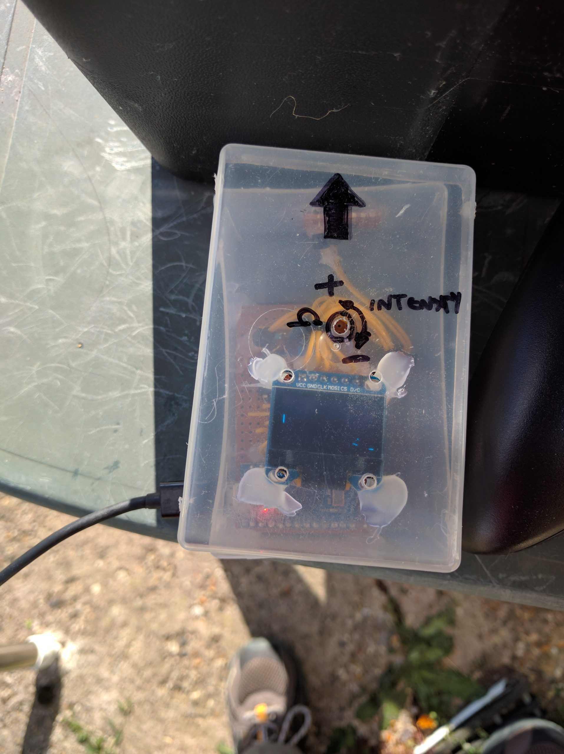
I used a plastic business card box as the enclosure for my SSSM. I fixed the main circuit board inside using a few blobs of hot glue. Holes were drilled (not very neatly) for the USB socket on the Pro Micro, access to the adjustment screw on the variable resistor and for the photo-diode. The photo-diode circuit board was hot glued in to place and protected with a plastic lens cover from an old torch, also glued in to place.
The optional OLED display was glued to the underside of the transparent lid and the lid secured using some computer case-fan screws (which bite well in to soft plastic without needing bolts to secure them).
Step 16: Using the SSSM
To use the SSSM within FireCapture you will need the SSSM plugin developed by Joachim Stehle and freely available from here: http://www.joachim-stehle.de/sssm_eng.html
The FireCapture plugin allows you to do two useful things:
- Monitor the seeing conditions and display a seeing quality graph over time.
- Control your imaging camera so that FireCapture automatically captures images when the seeing conditions meet a quality threshold that you define
Documentation on installing and using the plugin are available here: http://www.joachim-stehle.de/downloads/SSSMon/SSSMonPluginManual.pdf
If you regularly take solar images using FireCapture, remember to disable the SSSM plugin under the Preprocessing section of the control window when you’re not using it. If you forget, FireCapture will go through the motions of taking recordings (including the various reassuring beeps and on-screen displays), but when you look closely you will find that no frames are actually being saved. It’s an easy mistake to overlook!
Joachim also offers stand-alone Windows software for capturing and graphing the output of the SSSM from the download page linked above. As you can see from the serial monitor, the output protocol from the SSSM is very simple. Developing your own software to read and use values from the SSSM would be relatively simple for an intermediate-level developer.
Step 17: Adding an Optional OLED Display
This section is recommended for slightly more advanced electronics types as I can’t give you definitive instructions for every module that is sold. Proceed at your own risk, but generally speaking there isn’t much risk of breaking your Pro Micro or OLED module if you mess up the wiring a few times!
Miniature OLED display modules can be obtained from eBay and elsewhere for a few pounds/dollars. Adding one enables the SSSM to be used stand-alone without a computer, provided you can supply power through the USB port. Many astronomy power tanks now have USB charging output sockets for example.
You will want a Monochrome 128×64 or 128×32 OLED module that supports Hardware or Software SPI (the communications protocol that the Pro Micro will use to drive the OLED module). Many modules support both Hardware and Software SPI, plus IC2 (a different communications protocol) depending on how you wire them up and which jumpers you connect or break on the module board.
The main difficulty is that you’re never quite sure what you are going to get by way of a module from the seller’s description. The vast majority can be made to work but you will very likely have to do some experimentation, a bit of guesswork and read a number of documents and web pages translated badly from the original Chinese! Do your testing on a breadboard first; you don’t need the rest of the SSSM circuit to be attached to the Pro Micro for this purpose.
I have used Hardware SPI in the rest of this build; the main difference being that the Pro Micro (and other Arduinos) have specific pins that can be used for Hardware SPI, whereas for Software SPI you may use any available digital pin for each of the control lines (and define them in the sketch). There is a useful guide to the Pro Micro’s pinouts here: https://learn.sparkfun.com/tutorials/pro-micro–fio-v3-hookup-guide/hardware-overview-pro-micro and a guide to SPI here: https://learn.sparkfun.com/tutorials/serial-peripheral-interface-spi
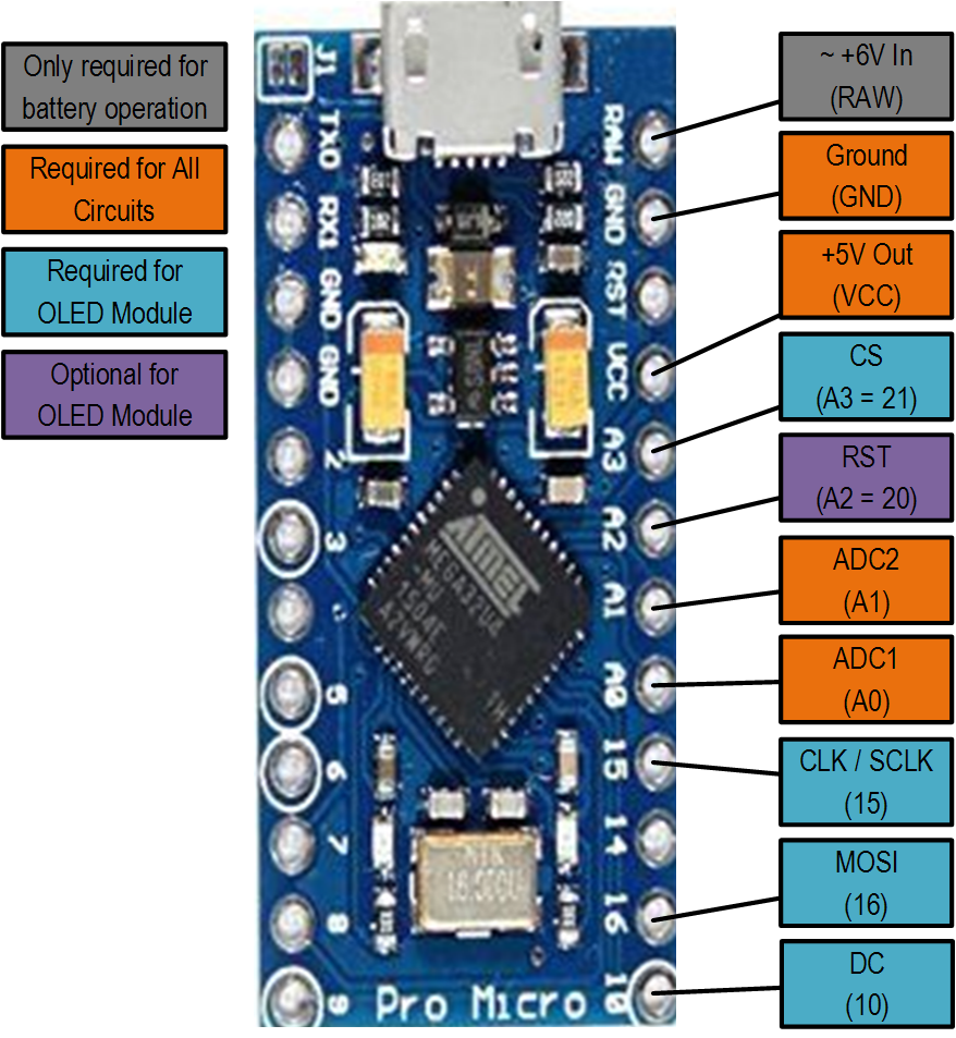
The first thing to be aware of is which connections are likely to be needed for the OLED module. The module will likely have six or seven pins (perhaps more or fewer depending!). Referring to the diagram below, in my set-up the OLED module will require connections from the Pro Micro to GND and VCC (to power it), plus CS, CLK (or SCLK on some modules), MOSI and DC. You may also need RST but my module didn’t have this pin available.
If you have a module that can support both SPI and IC2 protocols, you may find some of the pins are labelled only for the IC2 mode, leaving you to guess/Google to figure out their function when using SPI mode! Good luck!
Secondly you will need to add the appropriate graphics support libraries to the Arduino IDE. AdaFruit offer a bunch of libraries here: https://learn.adafruit.com/adafruit-gfx-graphics-library/overview
The two that are typically needed for OLED modules are as follows:
- The Adafruit_GFX library for Arduino which provides a common syntax and set of graphics functions: https://github.com/adafruit/Adafruit-GFX-Library
- The Adafruit_SSD1306 support library for the Monochrome 128×64 and 128×32 OLEDs: https://github.com/adafruit/Adafruit_SSD1306
Note that you may need a different support library depending on the module you are using – check the seller’s page for information, or of course you could buy a module from Adafruit as then you’ll know what you’re getting!
Instructions for installing libraries in the IDE can be found here: https://learn.adafruit.com/arduino-tips-tricks-and-techniques/arduino-libraries
Prepare the hardware first:
- Insert the Pro-Micro in to a breadboard – make sure you orient it so that each pin is on a different track!
- Insert the OLED module in to the breadboard (after attaching the header pins if necessary).
- Connect the OLED module to the appropriate Pro-Micro pins by referring to the pinout diagram above.
Next prepare the sketch:
- Uncomment line 62 so that OLED_OUTPUT is now defined and thus the OLED driver code is included in the sketch.
- Assuming you are using Hardware SPI mode, check that line 67 (#define SOFTWARE_SPI) is commented out, and 68 (#define HARDWARE_SPI) is not commented out.
- Check the pin numbers defined in lines 78 through 80. If you’re using my wiring scheme as per the pinout diagram above, you shouldn’t need to change these. In my case there was no RST pin on the OLED module, so OLED_RESET is defined as -1 (ignore). If you do have a RST pin, connect it to an unused digital pin and insert the pin number at line 78 (note that some pins may have an analog pin number “Ax” and a digital pin number “xx” and it is the digital number that should be used.
If you wish to use Software SPI mode, the you just need to connect VCC and GND, wire each of the communications lines to any available digital pin and define the pin numbers in lines 75, 76, 78, 79 and 80.
- Next, open and edit the Adafruit_SSD1306.h file. Note that this will usually be in the folder “Documents > Arduino > libraries > Adafruit_SSD1306” on Windows machines. Search for the comment “SSD1306 Displays” and then follow the instructions to uncomment the correct line for your module just below. Save the library file.
Now use Sketch -> Verify/Compile to check your work, and when you’ve dealt with any errors, Sketch -> Upload. All being well, when the Pro-Micro starts up, the display should briefly show the SSSM splash screen and sketch version numbers, and then display the “Seeing:” and “Input:” (intensity) values numerically, plus top right a small graph showing the history of intensity readings, and in the main part of the display a larger graph showing the history of seeing values.
If the intensity value is too low or too high then “LOW” or “HIGH” will be displayed instead of the intensity history graph. Either wait for full sunlight or re-calibrate by adjusting the variable resistor as necessary.
Depending on the size of display, the sketch will attempt to scale the graphs to fit or not display them if there is insufficient space, but your mileage will vary and you may have to dig in to the code if you have an uncommon display size.
Once you are happy the OLED display is working correctly, attach the module to a separate piece of strip-board and then connect that to the main board using connector wires in a similar manner to the way the photo-diode was connected. Now head back to Step 15 to box up your new SSSM.
Hi,
think there is a small glitch in your Arduino Code. You have .5 as default DC offset. Think this should be .05 which is the value in the original sketch from E.J. Seykora: ValueB=ValueB-.05; // + or – small dc off-set
When I was testing this code I noticed much more optimistic seeing values than with the original code on the same device with same calibration. Typo error or a specific reason why this is set to .5 in your code?
Regards,
Paul
Hi Paul,
You’re absolutely right. It’s an error that crept in when I was testing one of the PC-side tools that wouldn’t accept seeing values that were higher than it expected. I used the offset to force values that would work, and forgot to change it back in the published version. Thanks for spotting this; I’ll fix it when I get five minutes!
Anyone still here? Anyway.
I built one myself and everything seem to work even the firecapture plugin BUT how do I know if the photodiode is working? I bought a pack of 10 from aliexpress and all of them behave the same. They don’t respond to any kind of light (blue, red, LED flashlight, sunlight) and even when completely dark the seeing value pretty much stays at the same level ~ 3 and fluctuates up and down a little. I tripple checked the wiring and it’s correct so my guess is that not all BPW34 diodes are the same even the ones with anti IR coating.
Hi, it’s been a long time since I built it. I think there are two types with and without the anti-IR coating. It’s a bit hard to know what the issue is to be honest. It should be pretty obvious that the readings change if the light is blocked and unblocked. If you’re seeing no change in the readings (try printing them to the serial monitor by modifying the Arduino sketch) then something is definitely amiss.
Hi,
thank you very much for posting the “how-to”. With the help of your guide, I was able to successfully build SSSM – works great under the IDE interface. However, if I switch to the real life mode (without IDE interface), neither the WIndows software nor the FireCapture does work: Using the Windows software, I can connect to the SSSM and get sometimes one reading; FC says there is no COM-port available. Switching back to the IDE interface, everything runs as expected. Any ideas what is causing this behaviour? Thank you for your help in advence!
Hi Don, most likely the issue is that the Pro Micro and clones behave differently that other types of board in relation to serial comms flow control. The IDE copes just fine with the different types of board as the drivers know whether to use RTS/CTS (hardware control) or XON/XOFF (software control). A lot of external software seems to assume one scheme or the other and being able to communicate in the IDE but not in third party software suggests this may be the issue. Your only options are to either have the driver modified (probably not an option for the FC module) or to switch board type. If you’re using a pro-micro/leonardo clone, switch to the other type of board – AFAIK the pro-micro worked for me. That’s not the best news I know but I’ve had similar issues with other projects.
Hey bud, i dont suppose youd be willing to make one of these for one of my astrobiscuit videos, (im a youtuber called astrobiscuit) I’d pay for it of course…
thx Rory
Hi Rory, sorry for the late reply. Unfortunately work consumes too much of my available time to be able to do so.