In my previous post about dew formation and prevention, I explained why dew forms on your imaging gear and outlined some simple strategies for combating it. Perhaps the most effective of these is to use a Dew Heater Band to keep your telescope optics just above the dew point.
There are many commercial suppliers of dew heater bands, but they tend to be rather expensive and range from £20 for a small eyepiece heater to £70 or more for a large band to heat a 36cm scope. Making your own dew heater band is a much cheaper option and for a few pounds in materials and a small amount of effort you can make one every bit as effective as a commercially bought model.

The basic principle for building a dew heater band is very simple; you make a flexible band out of something which conducts electricity but has an appropriate amount of resistance, wrap it around your telescope objective/corrector and pass an electric current through it. When you pass electricity through a resistive element, it gets hot, and that in turn heats your telescope and keeps it above the dew point. Resistive heating elements are used in household electric heaters, toasters and car windscreen heaters.
One means of creating a dew heater band is to use electrical Resistors strung together in series or parallel to generate the necessary heat. These are quite effective for heating small things like eyepieces and secondary mirrors in Newtonian telescopes, but for larger bands they are more expensive to build, involve much more soldering and I suspect that they are also more prone to breaking due to the inflexible connection wires coming out of the resistors.
Most of the larger commercial dew heater bands use Nichrome Wire for the resistive element. Nichrome wire is an alloy of nickel, chromium and iron. It is strong, flexible, can withstand very high temperatures and is available in a whole variety of gauges (thicknesses) with different resistances. It also has the advantages of being readily available and cheap. If you peek inside your toaster next time you are making breakfast, the glowing elements that you will see are made from nichrome wire.
How Hot?
Nichrome wire can generate a lot of heat, but we just want to keep the optics of our scope above the dew point, not toast them to a crisp. Whilst it is easy enough to state that our aim is to keep the optics 2 or 3 degrees Celsius above the dew point (a moving target itself), there is no straightforward way to calculate the appropriate temperature of the dew heater band to achieve this, nor the power needed to attain that temperature. The properties of the heater band and the telescope, plus the environmental conditions make it too difficult to do anything other than make an educated guess based on experience.
Typically heater bands are used with a dew heater controller which reduces the power output if it is too high for the prevailing conditions. Usually the operator is responsible for monitoring things, but some enterprising souls have built micro controller driven devices that use temperature probes to monitor ambient conditions, the temperature of the optics and to increase or decrease power as required.
Our main concern is finding a maximum output level that is sufficiently high to cope with the coldest nights but not so high as to be dangerously hot when the band is on full power and not attached to the scope. (The band will get much hotter than normal if it is powered up and not attached to anything).
After a bit of research on commercial telescope bands and the experiences of other builders, I determined that I needed a dew heater band that gives out about 0.3 watts per cm of its length would work for a range of scopes from an 80mm refractor up to a 20cm SCT. A bit more or a bit less power would not do any harm, but you should exercise caution as a mistake could result in burnt fingers or expensive damage to your equipment (remember the toaster!)
Following feedback from readers, if you are building a heater for a smaller device such as a DSLR lens, an eyepiece or anything made of plastic or containing oil, grease or moving parts, start with an output lower than 0.3W/cm. Alternatively use a dew heater controller to limit the output. Small devices have much less volume so heat up more quickly, and oil/grease can become mobile damaging things if heated beyond the manufacturer’s stated operating temperature range. I’ve been told that 0.06W/cm works fine for a small DSLR lens. Basically, if you can feel the device getting warm or hot to the touch, you are applying too much heat so dial it down!
The rest of this article assumes you are using a medium or large telescope, and to give you an idea of what you are aiming for, once I had fully constructed the heater band and enclosed it in duct tape, 0.3W per cm felt safe to hold in the hand without the risk of burning, but just starting to verge on the uncomfortable. Conversely, when the band is attached to the scope, both feel cool to the touch. The scope acts as an effective Heat Sink (which is the object of the exercise of course). Make sure you monitor the temperature of your band over a reasonable period of time (30 minutes or more) to ensure that it does not heat up over time.
I operate my equipment in temperatures of between -5 and +10 degrees Celsius; above this dewing tends not to be a problem and below it I am staying indoors! If your climate is much colder or hotter than this, you may need to adjust the power output of your dew heater band to compensate. It is also worth bearing in mind that I have used these heater bands on scopes with diameters of 80mm (refractor) and 200mm (SCT). If you have a really large SCT you may need more power output to get heat all the way to the centre of the corrector plate.
Placement of the Dew Heater
With my refractors, which have built in metal dew shields, I find that wrapping the heater band around the outside of the dew shield a couple of centimetres in front of the objective is most effective. This heats the thin dew shield from outside and causes it to radiate heat on to the objective without needing to heat the whole body of the OTA. I don’t need to add a secondary foam dew shield in this scenario, though doing so might be worthwhile as I could then reduce the power of the heater band.
With the 20cm SCT, wrapping the heater band around the outside of the corrector plate holder is the best arrangement I could manage. A foam dew shield is then pulled over the top of the OTA and heater band, preventing the heat from radiating away from the scope. It is less efficient as the heat has to conduct through the thick metal ring holding the corrector plate rather than radiating on to it. With a bit of effort I imagine I could make a metal liner for the foam dew shield to act as a more efficient radiator and reduce the power of the band correspondingly.
Materials
You will need the following materials to construct a dew heater band:
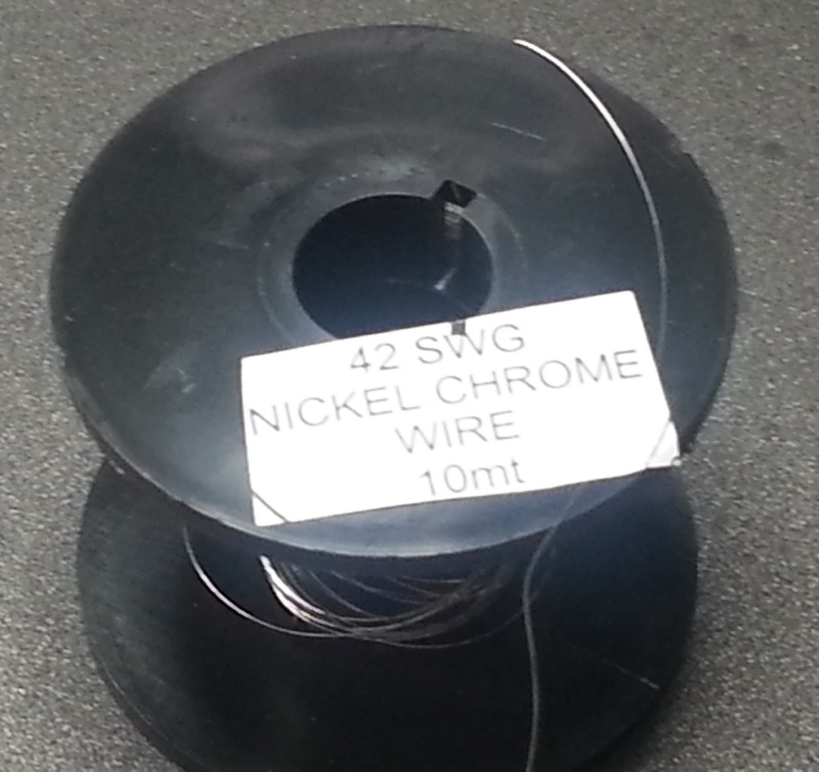
- Nichrome Wire: This is available in many different gauges (thicknesses). Note that the thinner the wire, the higher the gauge number (SWG or AWG) and the greater the electrical resistance. If you can look for an estimate of the wire’s resistance (in Ohms) per metre of wire, othewise you may have to experiment with a selection of gauges to find the best one. (I found that different sellers would quote different values for the same gauge of wire suggesting that they were either slightly different alloys with varying resistances or that the figures were less than reliable.)
- See the calculations section below for the method of calculating the appropriate resistance per metre for your needs and the length of wire you will require. Bear in mind that the supplier’s quoted resistance per metre will be an estimate and you will have to measure the actual resistance yourself once purchased. This in turn may affect the length needed. I bought both 32SWG and 42SWG wire to experiment with, and to be on the safe side double the length required from my calculations.

- Insulated Copper Wire: You will need some insulated copper wire to make attachments to the nichrome wire and possibly to make a non-resistive return leg for the heater band. Use braided wire rather than solid copper wire (for flexibility). Good quality speaker wire or electrical hook-up wire will do the job and is available from any electronics supplier or on-line.

- Thick Speaker Wire (i.e. twin conductors): You will use this to connect the heater band to the power source; don’t forget to allow sufficient slack to permit your scope to rotate freely on its mount.
- Note: I will show you how to calculate the total current in your heater band and the connection wires below. You need to make sure your copper hookup and connection wires are thick enough to carry that current without melting; as a rule of thumb you need wire that is 1mm – 1.5mm in diameter.
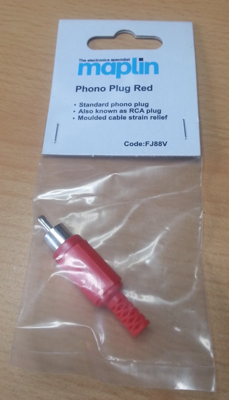
- Phono Plugs and Line Sockets: Most commercial dew heater bands and dew heater controllers use phono sockets and phono plugs (also called RCA connectors) for connections. For each heater band you need one phono line socket for the connector on the band, a phono plug on the connecting cable, and depending on your power source you may need a second phono plug at the other end (or some other type of connector). If you are planning to use multiple bands at once, use different coloured plugs and sockets for each set to avoid confusion late at night! (I’ll show you how to make a cheap dew heater control box in a later post).
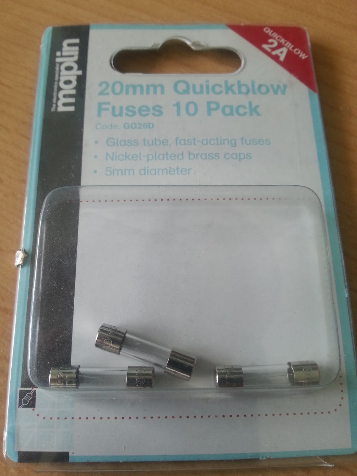
- A Fuse and In-line Fuse Holder: You are advised to add a fuse between the dew heater band and the power supply. If you get a short circuit or make a mistake, the nichrome wire will not melt, so you will need a fuse with an rating of slightly more than the expected current draw of your heater band to prevent a fire or equipment damage. If you are planning to build a dew heater controller (details coming in a later post) the fuse can be built in to that, otherwise you will need an in-line fuse holder.
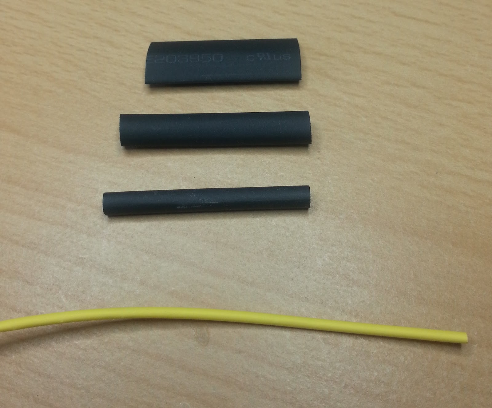
- Heat Shrink Tube: Buy a pack of different sizes of heat shrink tube. You will use this to insulate the connections at the ends of the heater band. If you find you need to build a “series” type heater band (see below), you will also need a long length of heat shrink to insulate each turn of nichrome wire.
- Duct Tape: This will be used to wrap the whole heater band to give it strength and further insulation. Make sure you use non-conducting tape, not tape with a metallic coating on one side.
- Self-Adhesive Velcro: This is used to join the two ends of the heater band once they are wrapped around the scope, allowing it to be removed when not required.
- (Optional) Foam Insulating Strip: Self-adhesive strip used as draught proofing around doors and windows can be used to make your heater band more efficient. By insulating the outside of the band, you can ensure that more of the heat is directed inwards to the scope.
Equipment
You will need the following equipment to construct your heater band:

- A Power Source: I used a cheap 12 Volt Laptop power supply (again from eBay) to power my heater bands, as I image where I have access to mains power. We will calculate the total power requirement of the heater band(s) below, so make sure your supply can supply enough current (Amps). Alternatively you may be using a power tank or 12V battery to run your equipment already if you are out in the field.

- Clearly you need to make sure any mains-powered equipment is operated via an RCD (which will cut the power in the event that it decides to make its way to earth via your telescope or your body!) and that it is protected from the elements in a waterproof but ventilated enclosure.

- A Soldering Iron and Lead Free Solder: There is a small amount of soldering required to hook up the wires and connectors, but nothing too taxing, honestly! A pair of ‘helping hands’ and a soldering iron holder are also a good idea.
- A Multi-Meter: You will need to check the resistance of your heater band so this is an essential piece of equipment for the job.
- A Ruler or Tape Measure: The length of Nichrome wire is a critical to the construction process, so measure twice, cut once!
- Optionally, you might search for ‘Copper Fishing Crimps’, which can be used to join the nichrome to the copper wire instead of soldering. I haven’t tried this myself though.
The Theory
Now we need to do some maths to figure out how to construct a heater band which gives out 0.3 Watts per cm of length.
First of all, I will run through some worked examples to show you how to calculate the appropriate resistances, lengths, etc. After that I will provide a spreadsheet to do the necessary calculations for you. In all of the calculations below, the following terms are used:
- Rm: Resistance of Nichrome wire per metre as measured above (in Ohms)
- Cb: Length of Band – OTA Circumference plus overlap (in cm) (see below for details)
- Rt: Total resistance of the heater band (in Ohms)
- Vs: Power supply (in Volts)
- Is: Current drawn from power supply (in Amps)
- Ot: Total output of band (in Watts)
- Oc: Output of band (in Watts per cm)
- Ws: Length of the nichrome wire (in cm) (for a series circuit)
- Ts: Number of turns of wire around the OTA (for a series circuit)
- Np: Number of parallel runs of wire (for a parallel circuit)
- Wp: Total length of the nichrome wire (in cm) (for all runs in a parallel circuit)
- Rp: Resistance of a single run of wire (in cm) (for a parallel circuit)
Power
Remember, we are aiming to make a band which gives us a value of Oc which is approximately 0.3W per cm for a telescope, less for smaller devices. The total power output in Watts (Ot) is simply the power output in Watts per cm (Oc) multiplied by the length of the band in cm (Cb):
Ot = Oc x Cb
So for example I needed to make a 32cm band for a refractor, and with a power output of 0.3W per cm the total power output of the band is 9.6W (0.3 x 32 = 9.6W).
Current
To calculate the current drawn in Amps (Is) given that we know the required total power output of the band (Ot) and the voltage of the power supply (Vs):
Is = Ot / Vs
I am using a 12V power supply and want a power output of 9.6W, which gives me a current draw of 0.8 amps (9.6 / 12 = 0.8A).
Note: You must use a low voltage power supply in the region of 5 to 14 Volts. Using mains voltage in the heater band is a very bad idea indeed, since you will cook the end of your scope if you are lucky, and electrocute yourself if you are not.
Resistance
To calculate the total resistance in Ohms (Rt) needed to draw a specific current in Amps (Is) from a known power supply in Volts (Vs):
Rt = Vs / Is
I want to draw 0.8A from my 12V power supply so I need my nichrome wire to have a resistance of 15 Ohms (12 / 0.8 = 15 Ohms).
Series or Parallel?
Finally we need to figure out the best way to create the required total resistance in Ohms (Rt) using our nichrome wire. Remember we already know the average resistance of the wire in Ohms per metre (Rm). There are two basic choices; either a series circuit or a parallel circuit.
Series Circuit
One way to make the band is to use a series circuit, i.e. single run of nichrome wire which loops back and forth several times. Refer to the schematic for details of this arrangement. Note that if we end up with an odd number of turns of nichrome wire, we need to make a final return leg out of copper wire to bring the circuit back to the start of the band. The copper has virtually no resistance so does not affect the power output.

We need to calculate the necessary total length of the nichrome wire in cm (Ws) to create the desired resistance:
Ws = Rt / (Rm / 100)
I have some nichrome wire which I have measured as having a resistance of 13 Ohms per metre, and I want a total resistance of 15 Ohms, so I need approximately 115cm of wire (15 / (13 / 100) = 115.38cm).
Finally I need to calculate the number of turns (Ts) that would make around my OTA including the overlap (Cb), as follows:
Ts = Ws / Cb
My OTA circumference plus the required overlap is 32cm, so the required nichrome would wrap around 3.6 turns (115 / 32 = 3.59 turns around the OTA).
If you get a result which is less than 1 turn, use the parallel circuit calculation below. If you get a result which is not a whole number of turns, simply increase the overlap figure until you do get a whole number of turns. You will end up with a longer band but it will still work.
By increasing the overlap at the end of my band from 3cm to 6cm, I can create a band which has 105.49cm of nichrome making 3 turns around the OTA and gives out 0.3W per cm (105.49 / 35 = 3.01 turns, close enough!)
Parallel Circuit

The other option is to use a parallel circuit, i.e. several parallel runs of nichrome wire. Refer to the schematic for details of this type of circuit. Note that in all cases we need a final copper return leg to bring the circuit back to the start of the band.
All of the parallel runs of nichrome must be the same length as the band (Cb). First we need to calculate the resistance of one run of nichrome wire (Rp):
Rp = Cb x (Rm / 100)
So for a 32cm band, one run of nichrome would have a resistance of 4.16 Ohms ( 32 x (13 /100) = 4.16 Ohms).
We can then calculate the number of parallel runs needed (Np) to create the required resistance:
Np = Rp / Rt
So to create a resistance of 15 Ohms from parallel runs of 4.16 Ohms we would need 0.28 parallel runs (4.16 / 15 = 0.28)! Clearly this is impossible as we can’t have less than 1 run of nichrome wire (so we use the series result above instead).
If you get an result which is less than 1.5 parallel runs, use the series circuit calculation above. If you get a result of 1.5 runs or more, increase the overlap until you get a whole number of parallel runs. Again the band may be longer than you need, but it will still work fine.
If you end up with a crazy number of parallel runs you may want to look for thicker wire with a lower resistance per metre (but since we will end up twisting the parallel runs together in to a wire ‘rope’ during construction, using lots of runs is not a major issue. The wire is generally priced by weight so the cost of a long length of thin wire is roughly the same as a shorter length of thick wire anyway.)
N.B. It is important that all the parallel runs are the same length and have as near as you can manage the same resistance. The simplified calculation above relies on this being the case; if you need to use parallel runs of wire with different resistances, please refer to this detailed description of the necessary calculations for resistors in parallel.
Finally we can calculate the total length of nichrome wire required for the parallel circuit (Wp) as follows:
Wp = Cb x Np
Other Designs
Other designs are possible. For example you could make a variation of the series circuit by coiling the nichrome around the OTA in a helix rather than doubling back and forth in turns. This might suit a permanent observatory set-up if you do not need to remove the heater from time to time, as the ends of the band would be permanently joined.
A combination of the parallel and series design is also possible, where you make a heating element out of several parallel runs, but then arrange that element in a series of turns in the band (or indeed in a helix around the OTA). The possibilities are endless, but I am going to stick to the two basic designs set out above as these should work for most small telescopes.
The Spreadsheet
I have created a spreadsheet to help you perform the necessary calculations:

You can obtain a copy of the spreadsheet from Google Docs Here. You can’t edit the shared version directly, so what you need to do is:
- Go to the link above. Choose “File -> Download As” from the Google Docs menu and save a copy of the document in either Excel format or Open Document Format.
- You can then open the saved copy of the file on your PC if you have it relevant application installed, e.g. Microsoft Excel or one of the free office suites which support the Open Document format.
- Alternatively you can create a free Google account and open your saved copy in Google Docs using the ‘File -> Open’ menu.
Spreadsheet Step 1
Determine the ideal resistance per metre you want for your nichrome wire:
- Measure the circumference of the the outside of the telescope tube (OTA) or the dew shield if that is where you plan to fit the band. I simply wrapped a bit of string around my refractor’s dew shield and then measured its length. Bear in mind that the OTA will usually have a circumference that is greater than you would calculate from the diameter of the objective or mirror, which is why it is best to measure it directly. Enter that figure in the green box labelled “OTA Circumference” (in cm).
- You also need to allow some additional length for the band to overlap so you can join it together with Velcro, and also to allow for a bit of inflexibility and a few kinks and bends in the nichrome wire (the heating element often turns out to be a bit shorter than expected once assembled). Allow perhaps 10 to 15% of the measured circumference. Enter the desired overlap in the green box labelled “Overlap Required” (in cm).
- Set the power output required; the default is 0.3W/cm for a medium or large telescope, but you will want a smaller value for a lens or eyepiece (perhaps a tenth as much).
- Finally check the “Power Supply Voltage” you expect to use. This is set to 12 Volts by default, but you can adjust if you are using a 5V or a 13.8V supply for example.
- Sanity check the “Current Drawn” figure. This should be in the range of less than 1 Amp for a small 80mm scope to perhaps 3.3 Amps for a large 16cm scope. Again for a lens or similar, the current drawn should be much lower.
- Now check the “Series Circuit Results” and “Parallel Circuit Results” sections at the bottom of step 1. You will see the ideal resistances in Ohms per metre for a variety of scenarios; 1 to 4 turns for series circuits, and 2 to 4 runs for parallel circuits.
- If you want to try more turns or runs, you can adjust the green ‘User Entered Turns’ and ‘User Entered Runs’ values yourself.
- Finally you can head off to your favourite electronics store or on line emporium and look for nichrome wire which most closely matches the calculated values. Bear in mind that not all the values calculated are actually available and that you are unlikely to find an exact match.
- Once you have found a few candidates, plug the quoted resistance per metre figures from the suppliers in to Step 2 of the calculator to sanity check them before you press the ‘Buy Now’ button. This will also calculate the required length of wire in cm (Ws for the series circuit or Wp for the parallel one).
- I’d suggest buying more wire than you think you need. For one thing the the resistance may turn out to be lower than quoted. For another thing you will need 6 to 8 cm of additional wire for a series circuit or 6 to 8cm for each run in a parallel circuit in order to make the connections to the copper wires.
Spreadsheet Step 2
You should carry out the next step once you actually have the wire in hand. (Before buying your wire, carry out a dry run of this step using the supplier’s quoted resistance per metre figure to find out how much you are likely to need).
- Measure out one metre of nichrome and then use your multi-meter to measure the actual resistance of that metre in Ohms. (Make sure you set the multi-meter to Ohms, not KOhms or MOhms!) You don’t need to cut the wire at this stage, just attach the probes to a stretched out length the wire one metre apart. Take care to avoid short-circuiting the wire on itself so that you get get a true reading. Make a couple more readings on different lengths of the wire and average the result.
- Now enter the average resistance per metre in the ‘Measured Nichrome Resistance per Metre’ box in the spreadsheet. Double check that you have the correct values for OTA Circumference, Overlap, Target Power Output and Voltage as we entered them during Step 1, as these will be re-used for the next set of calculations.
- Series: First check the ‘Number of Turns Round OTA’ under the Series Circuit Results section. If the result is significantly less than 1 turn, you will need to use a parallel circuit so skip ahead.
- If the result is a whole number (or very close to one), that is how many turns you will need so you can proceed to building your heater band.
- If the result is significantly more than 1 but not a whole number, increase the value of ‘Overlap Required’ gradually until you get as close as you can to the next whole number result for ‘Turns Round OTA’. You will end up with a slightly longer band as a result, but you can overlap the ends when fitting it so this is a not a problem.
- Parallel: If you didn’t get a satisfactory result with the Series Circuit, check the ‘Number of Parallel Runs Required’ value in the Parallel Circuit Results.
- Hopefully this number will be more than 1.5, (If it is less than 1.5 you should be using the Series Circuit Results). Again if it is close to a whole number, proceed to building using a parallel circuit.
- Otherwise gradually increase the value of ‘Overlap Required’ until you get reasonably close to a whole number of parallel runs.
- Note: If you get odd results please double check your measurements and data entry, or start over with a fresh copy of the spreadsheet. Bear in mind that you do not have to get things spot on and the spreadsheet is subject to rounding errors anyway. A band that is slightly too long can be overlapped a bit, and likewise a band that is slightly too short will still work (just use extra Velcro to join the ends).
- Our target of 0.3W per cm for power output is not precise, and a band that puts out slightly more or less than that will work. Feel free to deviate a bit from 0.3W per cm if it results in a more convenient band length, just avoid building one that puts out too much heat. I have not deliberately tried to set fire to my telescope in the interests of testing this, but I imagine 0.4W per cm would be OK. I’d definitely avoid exceeding that figure unless I was imaging in the Arctic.
Safety
Before proceeding to the build, a quick note about safety is in order.
The biggest risk in this process is short-circuiting the heater band and causing its resistance to drop dramatically. For example my SCT band using 12 ohm/metre nichrome is perfectly safe at 73cm length and draws a load of about 1.25 amps. If I managed to short it out by mistake or through wear and tear so the effective length is now only 1cm of nichrome, it would draw 24 amps = DANGER. As you know from looking in to your toaster, nichrome wire can withstand very high temperatures and there is a risk of fire in this scenario.
If you are using a mains power supply, something will either blow or trip fairly quickly unless you are using a welding power supply or something crazy, If you are using a battery or power tank, you may well get all the Amps you asked for and an unexpected and non-social visit from the local fire brigade. (Don’t believe me? Ask any local car mechanic why they disconnect the negative terminal of the car battery before working on it and every one of them will tell you about the guy who forgot and managed to weld a steel spanner between the positive terminal of the battery and the bodywork).
You should always use a fuse in series with the heater band that is rated slightly more than the current draw value (Is) that you calculated above. Even when using a fuse, a short can damage your power supply or heater controller, so if you are really concerned then do your own research on wiring in an ‘overvoltage crowbar’ which will also protect the power supply in case of a short.
As noted above, if you are using mains-powered equipment outside at night, you should connect it via an RCD which will cut the supply in the event that the electricity decides to go to earth via the telescope or via you.
Construction
Once you have designed your heater band, you are ready to start construction. The basic design is very simple:
- You will make the nichrome heater element and insulate it if required.
- Then you will attach the copper connecting wires, the fuse and phono plug.
- Next you will test the heater element.
- Finally you will wrap the heater element in several layers of duct tape and add the Velcro fasteners.
Making the Nichrome Heater Element
Before we start, it is worth knowing that nichrome wire is a bit tricky to work with. It comes on a roll (or a length cut from a roll at least) and it really, really wants to curl back up in to a roll. This makes it tricky to measure, cut and fix in to a nice flat band as it likes to whip around and spring out out shape:
- One thing that may help is to try to straighten the wire using heat. I took my wire, attached a weight to one end and then hung it from a hook. This pulled the wire straight and then I used a heat gun (for stripping paint) on a high setting and heated the wire a few times along its length. This took some of the curl out of the wire, but it still had a mind of its own.
- Other builders have suggested a similar process but using a naked flame to heat the wire until it is glowing, but I didn’t try that.
- Keep a few pre-cut lengths of duct-tape handy so that you can quickly stick the ends of the wire down on your work surface. This stops it getting tangled up as you work on it. A ‘helping hands’ tool and some small plastic spring clamps were also helpful when I was soldering connections.
Constructing the heater element varies according to the design you have selected. (You may find it helpful to refer back to the appropriate schematic above during this part of the process):
- Series Circuit, One Turn: This is the simplest design. Measure out the required length of nichrome wire (Ws on the spreadsheet), stretch it out and double check the resistance matches your calculations before you cut. Taping the wire to a non-conducting surface at each end may help you to measure accurately.
- Add about 4 cm at each end to give you some extra wire ‘tails’ for making the copper connections and then cut the wire to length.
- Series Circuit, More Than One Turn: This is the most complicated design. The first step is exactly the same as above. Measure the total length of wire (Ws), check the resistance, add 4cm tails at each end and cut to length.
- Next you need to insulate the full length of the wire, leaving the tails uninsulated. This is a vital step in the process as you need to ensure that each turn of the wire does not short-circuit on a previous turn once you have finished building the band. Remember, short circuit = much higher current draw = visit from the fire brigade!
- Use a long length of the thinnest heat shrink tube you can find. Bear in mind that the nichrome wire is probably going to be much thinner than the final diameter of the tube after you shrink it. I did not find this to be a problem as the propensity of the nichrome to curl up makes it grip the inside of the heat shrink tube so it doesn’t slide off easily.
- You will not be able to feed the wire through one continuous length of heat shrink as the thin, bendy wire will get stuck few centimetres inside the tube. Cut the tube in to sections (experiment to find a workable length) and insulate the bare nichrome by sliding a section of heat shrink tube over the wire. Shrink the first section in to place using a heat gun or the side of a soldering iron leaving a 4cm bare ‘tail’ for later. Slide the next section of tube over the wire until it overlaps the first section of tube slightly, shrink in to place and repeat until done, leaving another bare tail at the other end.
- Parallel Circuit: The parallel circuit is also relatively easy to make. This time you will need to make Np separate runs of wire, each of which should be Rp cm long. Measure, check resistance, add the 4cm tails to both ends of each run and cut to length.
- Now take all of the runs at one end and twist the 4cm tails together tightly as if you are making a rope. Next stretch all the runs out and twist together a few times, and finally twist the 4cm tails together tightly at the other end. Do not twist the main part of the runs too many times or you will end up with a heater element that is shorter than you require. You might find it helps to use short pieces of non-conducting duct tape to hold the runs together whilst doing this.
- Note that, unlike the turns in a series circuit, you do not need to insulate each parallel run from the others. The current travels through the whole element as if it were one ‘wire’ and it doesn’t matter whether the runs connect only at the ends, in the middle or touch along the whole length. (Think about braided copper wire if you’re not convinced about that).
Attaching the Copper Connections
The next step is to make and attach the copper connections to the ends of the nichrome heater element. Time for another important note about nichrome:
- You cannot solder directly to nichrome wire. Unlike copper, it does not ‘wet’ and the molten solder will just run straight off the wire. The usual method of dealing with this in industrial applications is to use crimp connectors to forcibly sandwich the nichrome and the copper connection wires together.
- I decided against this for two reasons. Firstly I was concerned that home-made crimp connections would not stand up to much wear and tear in the field. Secondly the nichrome wire I was using was very fine, and it would have been difficult to find a suitable type of electrical connector. It has since been suggested to me that copper crimps for fishing line might be suitable for the job, and a quick search for ‘Copper Fishing Crimps’ throws up many low-cost results, so you might try that if you want to avoid soldering.
- For my build, I followed the advice of other builders and used a ‘double noose’ arrangement to trap the nichrome wire inside the copper wire and then solder the copper wire to itself. I’ll describe the process below; it is quick and easy, and so far has proved very reliable in use.
Again refer to the appropriate schematic above for your chosen design. You will either need to make two short copper connections for a series circuit with an even number of turns, or a short copper connection plus a long copper return for the other designs.
- Use insulated, braided copper wire to make the connections / return. The wire needs to be thick enough to carry the current and typically 1mm to 1.5mm diameter wire should be OK. It also needs to be well insulated (particularly the return leg) as you do not want the nichrome to short circuit on the copper return for reasons you hopefully understand by now. I used 240v rated electrical hookup wire for the return as the thick insulation will withstand repeated heating by the adjacent nichrome wire.
- For the short connector(s) cut 10 to 12cm of copper wire and strip 4cm of insulation from one end.
- For the long return (if required), you need to measure a copper wire that is as long as the heater band. For the a series circuit with more than one turn, bend the heater element as shown in the appropriate schematic so that it is the right length for the completed band. Add 10 to 12cm at the connector end plus another 6cm at the far end of the return. Again strip 4cm of insulation from the far end.
- Next take the nichrome heater element, double the 4cm tail back on itself and twist to make a miniature “hangman’s noose”. Feed the stripped end of the copper connector through the noose, double it back on itself and twist to make a second noose. You should now have two nooses looped through each other.

- Now twist both nooses tighter until the nichrome and the copper are firmly locked together. Fold the nichrome noose back against the copper one and twist them together like a rope.

- Take your soldering iron and solder and use it to completely coat the copper noose all over. You want to make a fairly big lump or ball of solder around the copper so that it locks the nichrome inside.
- Use your multi-meter in resistance mode to check that you have a good connection from the copper to the nichrome wire.
- Cut a piece of heat shrink tube to length, slide it over the copper wire to enclose the solder joint and shrink it in to place. This insulates the connection and gives it a bit more strength.
- Connect the other connector/return to the opposite end of the heater element and insulate in the same way.
- Strip a small amount of insulation from the unconnected ends of the copper connectors/return and fit the phono line socket.
- Note: If you are connecting directly to the power supply, you will need to add the in-line fuse holder and fuse between the heater band and the phono line socket as well. Otherwise ensure that your dew heater controller has an appropriate fuse fitted.
- Make up the connecting cable from the heater to the power supply or dew heater controller. Cut an appropriate length of thick speaker cable (twin conductor), sufficient to allow your telescope to rotate on its mount fully. Fit a phono plug at the heater band end, and another phono plug (or other appropriate connector for your supply) at the power supply end.
- You could simply solder (or crimp) a long cable directly from the heater element to the power supply (with an in-line fuse), but using plugs and connectors makes it easier to set up and break down your equipment, plus there is less chance of damage should a cable get snagged in the dark.
Testing – Spreadsheet Step 3
Once you have built your heater band, but before you connect it to the power supply, you should check it meets your specification as follows:
- Measure the actual resistance of the band (in Ohms) using your multi-meter. Ensure there are no short circuits that would give a misleading reading and make sure you have the meter set to Ohms, not KOhms or MOhms. Open up the spreadsheet and put the result in the ‘Measured Resistance of Band” box.
- Measure the actual length of the heater element in cm. Put the result in “Measured Length of Band”.
- Measure the voltage of your power supply or battery using your multi-meter. Again make sure it is on the Volts setting, and put the result in the “Measured Power Supply Voltage” box.
- If you are using a mains power supply, check your power supply’s information plate for its current rating (in Amps) and put that in the ‘Rated Power Supply Current’ box. (Figuring out how long your battery or power tank will last is beyond the scope of this article I’m afraid; the Amp-Hour rating is a rough guide, but it is more complicated than that).
- Now check the ‘Power Output’ result, which should be reasonably close to 0.3W per cm, or whatever value you chose when designing the heater band.
- Also check that the ‘Power Drawn’ figure is less than ‘Rated Power Supply Current’ if you are using a mains supply. Don’t forget to add together all the current draws that you will be running from the supply. (Bear in mind that you shouldn’t run a cheap power supply continuously at its maximum rated current as you will considerably shorten its life.)
- Check that you have used a fuse between the power supply and the heater band that is the next available value above the ‘Power Drawn’ figure. This is particularly important if you are using a battery. If the fuse rating is too low, it will blow immediately and if it is too high the band could overheat if it shorts out.
- If you are happy that the measurements are giving the expected results, you can now test that the heater element works as expected. Lay the heater element on a dry, hard, non-conducting and non-flammable surface that you don’t mind damaging. Outdoors is a good idea for this step just in case!
- Connect the heater element to the power supply. Wait a few moments and check that it isn’t glowing red hot and that no other parts of the system are overheating. If the element is overheating, cut the power supply immediately and check your work.
- Now you can check whether the heater is getting warm or not. Don’t grab the thing in your hand; place your fingers above the element and feel whether it is is giving off detectable heat. You will have to decide for yourself whether it is safe to touch the heater element directly or not. Bear in mind that it will be giving out a fair bit of heat before it is wrapped in duct tape. Please use your common sense and don’t blame me if you get burned.
- If you have a temperature probe on your multi-meter you can use that to check the temperature of the element.
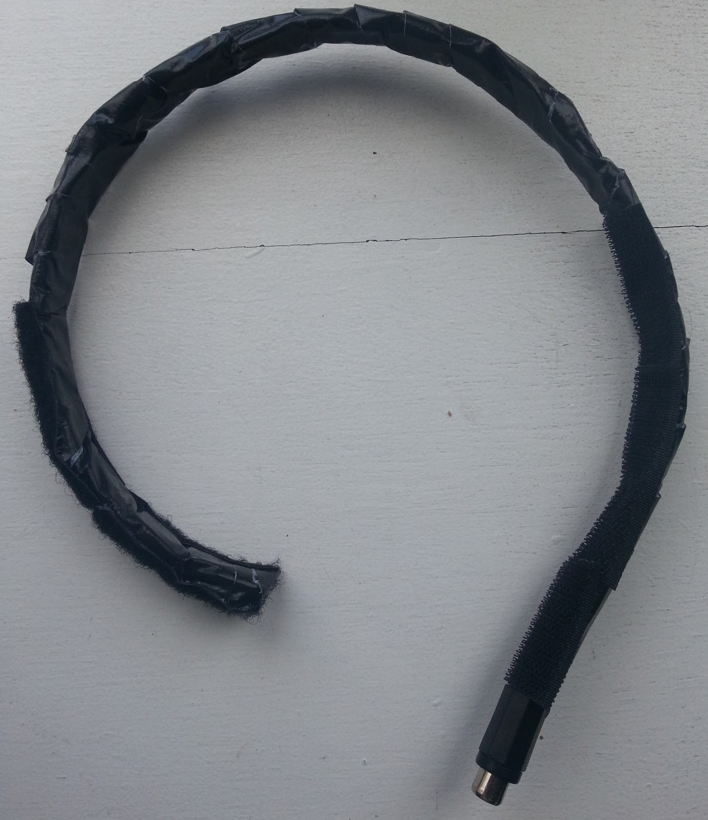
Wrapping the Heater ElementThe final stage in the process is to enclose the heater element to give it durability and to prevent it shorting out on the metal parts of your equipment. There are many methods of doing this including making fabric sleeves and other neat designs. I opted for the hobbyist’s favoured solution for all engineering problems, a quantity of duct tape!
- Use thick duct tape to enclose the heater element. Make sure the tape does not have a metallic coating to avoid the risk of shorts. Firstly cut a strip of tape that is as long at the heater band plus a few cm at each end.
- Lay the strip of tape on your work surface with the adhesive side facing upwards. I found that folding the extra tape back under the strip and sticking the ends to the work surface prevented things getting in to a tangle.

- Series Circuit (One Run) / Parallel Circuit: Lay the heater element on the adhesive surface of the tape just above the centre line and press it gently in to place. You may have to coax the element to lie in a reasonably straight line so take your time. The connectors and the phono plug should run out from the short end of the tape.

- Unstick the excess tape from the work surface and fold one of the long sides of the tape towards you, over the element and stick down. Next fold the other long side away from you, over the element and stick down.


- Series Circuit (More Than One Run): Lay each of the runs on the adhesive tape separately, leaving a gap to the next run. You will probably need to use the whole width of the tape for this.
- Cut a second long strip of tape and lay it adhesive side down on top of the heater element. Press the two pieces of tape together along the edges and between each of the runs. This will help to keep the runs separate and minimise the risk of a short.
- All Circuits: Stick the short ends of the tape together and trim off any excess. You should now have a tape ‘sandwich’ with the element inside and the phono connector sticking out of one of the short ends.
- If you have some foam insulation (e.g. self-adhesive draught-proofing tape for windows and doors) you can now use this to make the band more efficient. Stick the insulation to one surface of the band; whichever will be the outside when in use.
- Now cut a long strip of tape and wrap it around the band in a helical pattern from one end to the other, ensuring that each turn around overlaps the previous one. (You may find it easier to use several shorter lengths rather than using one piece).

- Finally wrap the completed band around your OTA to check for fit and and attach self-adhesive Velcro to both ends so that you can fit it tightly (the band needs to make good contact with the OTA all the way around).
- Perform a test to ensure that the band does not overheat the equipment. You should run it for at least 30 minutes, checking frequently to ensure that the equipment is not getting warm to the touch. If it is, turn down your dew heater controller or make a band with a lower output.
Hopefully your new dew heater band will now provide many years of good service. Prevention is better than cure, so remember to turn your heater on low before dew starts to form, rather high afterwards!
References
As with all my projects, I have relied on the advice of those who have gone before. References on building dew heaters include:
- Home Made Heater Strips With Resistors
- Home-made dew control for a telescope
- Making Dew Heaters
- Build a Dew Heater from Resistors
- DIY Astronomer Forum at Stargazers Lounge
Thank you for this how-to guide, even a lay person like me has been able to make a heater band for my DSLR. I had to make one that is powered off a portable battery pack with a 5V USB port, so the spreadsheet was incredibly helpful for working out the required resistance and length. Just tested the device and it seems to work perfectly. Will do a proper field test as soon as the sky is clear. Hopefully this will enable me to capture star trails for more than 1-2 hours at a time. Thank you again for this wonderful resource, you are great!
A word of caution:
The first dew heater I made following this guide had an output of approx 0.25 Watts per cm (below the recommended 0.3 W per cm). This output was too high and it damaged my lens pretty badly, so I would recommend a lower wattage (at least for DSLR users). The second version I made has an output of approx 0.06 Watts per cm, which is perfectly adequate for an ultra wide angle lens on a cold autumn night in the UK.
If you overheat your DSLR lens, the grease from the lens focusing assembly will leach out onto the diaphragm blades, delaying their action and causing blurry overexposure in your images. It will be costly to repair. The spreadsheet provided in this guide is very useful for doing the calculations but I would recommend to start at a lower wattage and if necessary work your way up.
Thanks for letting me know. The the guide is based on usage with telescopes not lenses so this isn't something I've come across or seen reported before. I'll modify the article to mention your experiences.
Great article! I am in the process of building the controller and bands but had a question about nichrome gauge. I had 32 gauge wire already and was wanting to use it for heater band on my 8in SC. When I do the math it gives me a length too short to circle my telescope (29in cir). 1 meter gives me 36.1 ohms. I'm using 12v power. I suspect that I need a smaller gauge wire. Appreciate any help.
OK here is what I get: 8in scope is 20.32cm diameter, circumference is 63.8cm. Add a bit for the tube and corrector fixing ring, and we are in the 70cm ballpark, agreeing with your 29in circumference, or 73.66cm. All good so far.
Put 73.66cm kn Step 1 of the calculator and a 8cm overlap which is reasonable for a tube this size. I can see there is a solution for 5 paralell runs of nichrome at 35.99 Ohms per metre.
Plug your measured resistance of 36.10 Ohms per metre in to Step 2, you get a solution that requires 5.02 parallel runs, which is close enough to 5 as makes no difference. You would need about 410cm of nichrome for that, about 13 and a half feet. Assuming your band ends up having a total resistance of 5.89 Ohms, your power supply would need to provide 2.04 Amps plus a safety margin.
If you have 14 or 15 feet of the 32 gague you are good to go. Just run it out to about 32 inches, then double back until you have five runs, twist it in to a rope and then go through tbe rest of the instructions.
If you don't have enough wire and need to buy some, get something with a lower resistance as you will need less of it. That means a wider diameter / lower AWG /SWG number if using the same alloy. Bear in mind that different alloys may offer different resistances though, so best if you can find out the resistance before buying. Price-wise it won't make much difference as the wire is sold by weight and getting the same resistance costs much the same regardless of the trade off between gague vs total length of wire.
best way to straighten nichrome is to put one end in a drill clamp other end in a pair of pliers straighten it out and turn drill on for a couple of seconds ends up nice and straight
Hello,
Instead of a phono plug, could I use a DC Power Jack Adapter Female Plug 5.5mm x 2.1mm like this: https://www.amazon.com/gp/product/B00QJAW9F4/ref=ox_sc_act_title_3?ie=UTF8&psc=1&smid=A2TWRNEH2276JE
Is the size of the wires that come with the plug a problem?
Thanks very much.
I used phono plugs because they have larger contact areas than some connectors giving a bit more headroom for higher current, and also because the thick speaker cable can be connected directly to the contacts (though you may have to trim/remove the strain relief to get it to fit). You’d probably be fine with what you suggest but it all depends on how much current is needed.
The other thing to think about is how secure the connectors are. Jack plugs tend to come apart very easily and could be an issue when slewing the scope around. Phono connectors are a lot more secure. The other option to consider is the XLR connector, which I have used on some other more recent projects. These are very secure as they lock together. They can also carry a lot of current, but are larger and more expensive.
Thanks very much for the quick reply! According to your calculator, I will be pulling 1.53 Amps. If I can ask another question, can you explain the pros and cons of a 1-turn heater versus a 3-turn heater? It would be a thinner wire versus a thicker wire, but I’m not sure what the consequences for power drawn or evenness of heating. Thanks again.
Nice write-up! I might have to build one of these myself. I did notice one issue, though. In the parallel run section, you mention the following:
“So to create a resistance of 15 Ohms from parallel runs of 4.16 Ohms we would need 0.28 parallel runs (15 / 4.16 = 0.28)!”
However, you’ve gotten your numbers mixed up when calculating. 15 / 4.16 = 3.61, not 0.28. So, you could absolutely create a set of parallel runs for your heater band.
Thanks for spotting the error. I had in fact transposed the 15 and the 4.16 in the example. The formula and the calculator spreadsheet are correct, as is the result as I should have put 4.16 / 15 = 0.28. Now corrected!
Question on the spreadsheet. I notice you have ohms per meter for series and parallel runs. Isn’t the result basically the same for two turns vs two parallel runs of 1 turn each? Or are you calculating the total resistance based on a single series run, and then doubling that? (i.e. you’re talking about 2 parallel runs of 2 turns each for the “2 parallel runs” row under parallel)
Okay, nevermind… it’s all coming back to me… parallel resistances are calculated differently.
1/R-total = 1/R1 + 1/R2 + 1/R3 … 1/Rn
So, if I run in parallel, it actually ends up being double, triple, etc. for the number of parallel runs on the ideal wire resistance.
Hi,
I have perhaps a rather question: what exactly do you mean by “overlap” with regards to OTA diameter? Why would the coils need to overlap at all?
Overlap means exactly what you have assumed. There is no requirement to have an overlap, but it is useful in two ways. Firstly if you are trying to achieve a specific power draw/output, you only have a limited number of choices in terms of the nichrome resistance per metre, so to fine tune the total resistance of the band you can make it a bit longer than necessary. Secondly, when attaching the band to the OTA, you might need to overlap it slightly to use Velcro strips.
Hello, I have made 3 dew heaters using 0.25mm NiC (22 Ohms) wire following your great guide and sort of following the figures on the spreadsheet… I have connected my 3 bands to a 12v power source with no in line control so in effect all are at max power for testing and surface temperatures recorded are:
Espirit 150 – 2 wire turns, 120cm length, max temp 33 degrees C
Evostar 72 – 2 wire turns, 58cm length, max temp 92 degrees C
Finder 50 – 4 wire turns, 76cm length, max temp 75 degrees C
Temperature was taken from the tube side which is insulated with duct tape the outside is insulated with duct tape and then an adhesive foam non of which seem to mind the temperatures being reached.
I hope to attach the finder band mid way in the hope it may keep both the objective and eyepiece clear. I will attach control knob to the Evostar 72 heater as seems far too hot, but not sure about the Espirit temperature whether this needs a control knob or not?
Clearly being wrapped around large tubes of steel and glass is cold temperatures will dissipate heat but is there an ideal off scope temperature the bands should reach?
Thank you
Peter,
I’m going to assume that when you say 22 Ohms, you mean 22 Ohms per metre of wire (per the measuring instructions). Remember you measure the resistance of a single strand per metre at the start of the project in step 1 and 2 (before making it in to a heater band). You then verify the resulting overall resistance of the entire band at step 3 after making it up.
Taking one example (the Esprit) the circumference should be in the region of 47-50cm (15cm x Pi). So for the two turns that would be a total length of 100cm of nichrome, so in the ballpark of 120cm you quote. At a resistance of 22 Ohms/metre the total resistance of the band would be 53 Ohms (2.4metre x 22Ohms/metre), and at 12 Volts you’d be getting a power output of 0.02 Watts per cm OF BAND LENGTH (not WIRE LENGTH. That’s really low. I’m struggling to understand why you are getting a temperature of 33 degrees C. Even if you mistakenly twisted the runs together you get total resistance of 13.2 Ohms and a power output of 0.09 Watts/cm, i.e. still low.
To get a heat output of about 0.3 Watts per centimetre for a 120cm band at 22 Ohms/metre resistance, 12 Volt supply, you would need between 6 and 7 parallel runs twisted together (i.e. making 6 or 7 lengths of 120cm nichrome and twisting them together to make a single thick “wire”).
I think you need to revisit the spreadsheet – start with a fresh copy and re-work the figures, but to short cut things, if you are using the 22 Ohm wire, for the three scopes you need:
Espirit 150 –120cm length, 7 PARALLEL RUNS (not SERIES TURNS)
Evostar 72 – 58cm length, 1 series turn or 2 parallel runs.
Finder 50 – 76cm length, 3 parallel runs.
(I’m unsure as to why you need a longer band for the 50mm finder than the 72mm Evostar though?)
If you don’t have enough wire for the above and need to re-buy, I’d suggest going for a heavier (thicker) wire gauge for a lower resistance to start with and re-do the calculations.
Hi Ian, I’m confused by your answer to Peter- could you explain a bit more? You say 22ohms per meter is high and that is causing the high temperature and then suggest twisting the wire into a thicker lower resistance parallel bundle. But that will reduce the resistance, increase the current and thus the power leading to even higher temperatures?
Hi Ian, I think the reason Peter is getting too much heat is that he has calculated the watts per cm on the total length of the wire. The problem is the wire is multiple turns so the total wattage per cm is the wire W/cm x number of turns so he is ending up with 0.4W/cm which might be a bit much according to your recommendations. The reason he needs a longer length for the finder is that he needs more turns to increase the resistance to reduce the W/cm to compensate the increased number of turns that sum up for total W/cm of the band.
I think you are confused about parallel windings- they increase wattage by reducing resistance and increasing current- power is I2R so increasing current increases power exponentially.
Mark
Hi Mark,
I’ve re-written my original reply to be clearer in case anyone else comes across it. You are correct my comment about the high resistance leading to high temperatures was wrong. Of course it is the opposite, high resistance = low temperature so I have corrected that. I have no idea why Peter’s numbers vs the measured temperatures are so far out. Using the information provided, there should be almost no heat being generated in any reasonable scenario I can calculate due to the high resistance in both the series and parallel scenarios. The fact he is generating so much heat tells me he has misapprehended something here about either measuring or calculating. I have provided the correct figures for wire of 22 Ohms/metre.
Thank you for your reply. Would you please be able to email me?
Regards
Greetings from the US,
Thank you very much for your very informative post regarding dew heaters. I have been wanting to undertake this DIY project for many years and am finally getting around to doing it. I will need at least 3 heater bands for my 12-inch Dobs: 1 for the finder, 1 for the eyepiece and 1 for the secondary holder measuring 19.4 cm, 22.5 cm (for my largest eyepiece) and 11.25 cm in length, respectively. Going through the calculations you outline, delivering 0.3 watt/cm, I would need to deliver 5.81 watt to the finder, 6.75 watt to the eyepiece and 3.375 watt to the secondary. Using a 12 V battery, this would result in required currents of 0.48 amp, 0.56 amp and 0.28 amp, respectively, with corresponding resistances of 25 ohms, 21.4 ohms and 43 ohms, respectively. Using a guage 32 nichrome wire (with R=0.33 ohm/cm), this would result in required wire lengths for the heater bands of 75 cm, 63 cm and 129 cm, respectively. I am having an intuitive problem in understanding why the shortest band (for the secondary holder) should require the longest length of wire (although I understand it results from the highest required resistance). It would seem that if 63 cm of wire is enough to deliver sufficient heat to a relatively large 24 mm eyepiece then that should be enough to heat the secondary. Did I miscalculate, or am I missing something here? I also wonder what your thoughts are about constructing a heater band using loops of nichrome wire or a sawtooth pattern for the wire across the band (along the lines of https://computer-ease.com/darkskies/dewstrp1.htm), rather than one linear piece, which would cut down on the length of band and the number of turns for wrapping the accessory. Thank you for any information and help with these issues.
Hi Woody,
Assuming constant voltage (12V), increasing the length of the wire increases resistance, which reduces current and so reduces power. So the shorter the band, the higher the resistance needs to be to keep the power output to 0.3 W per cm. Your calculations for the secondary seem correct to me. 9 turns is quite a lot to deal with, and ideally what you’d do is look for some thinner, higher resistance wire to reduce the number of turns needed.
Thank you for your reply Ian. My concern in going to a thinner wire than 32 guage is that it may be too thin to hold up to use over time. Thirty-two guage is only 0.2 mm in diameter. How thin a nichrome wire can you use for a durable heater element?