In this post the observatory is starting to take shape. We will finish the floor and build the plain walls (I’ll cover the wall with the door frame later).
The Floor
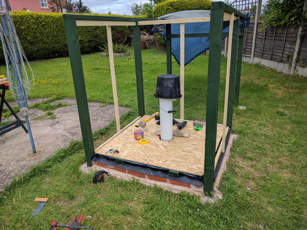
The first step was to lay the floor which was made from a sheet of 11mm Oriented Strand Board (OSB). I used basic OSB2, which is suitable for non-structural use, as it wasn’t going to be (particularly) load bearing. If you are planning to use OSB for structural or exterior use, you should use conditioned OSB3 instead.
I cut the OSB sheet to size using a circular saw; you could use a hand saw but it would take a long time to make all the cuts. Circular saws and similar power tools are dangerous if used improperly, so make sure you read and follow all the safety instructions. In particular, I made a saw table out of the remnants of the wooden pallet and a couple of roof battens to support the sheet when cutting. It is important to fully support both sides of the cut, otherwise the sheet can ‘fold’ along the cut line trapping the saw blade and causing it to jerk back or up suddenly and forcefully, causing serious injury.
Cutting the floor was slightly challenging due to the fence post frame being a couple of centimetres off square. I then marked out the pier position and cut a circular hole in the floor to accommodate it. I did this using a hand drill with a large hole saw to cut holes around the inside of the circumference, before joining them up with a small hand saw. I also used the hole saw to cut two holes for the flexible conduit.
Next I cut out a piece of vapour barrier membrane with a hole to fit over the pier and stapled it to the floor support frame. This is an important step to keep damp out of the observatory interior and protect the woodwork for longer life. Finally the OSB sheet was dropped over the pier and on to the floor support frame, remembering to thread the electrical conduit through the relevant holes. I then screwed the floor to the frame, making sure to use a countersink bit to recess the screw heads.
[box type=”info” style=”rounded” border=”full”]I used 30, 40, 50 and 60mm screws for the whole construction rather than nails. This made it easier to take things apart again should the fit not be right or if I wanted to modify the design as I proceeded. I would recommend using ‘Ultra Gold’ or ‘Turbo Gold’ type wood screws available from various suppliers. They are a bit more expensive than standard wood screws, but much faster and more accurate to use. I found that drilling pilot holes was only necessary near the end grain of timber or when fitting the shiplap.[/box]
Wall Framing and Inner Wall
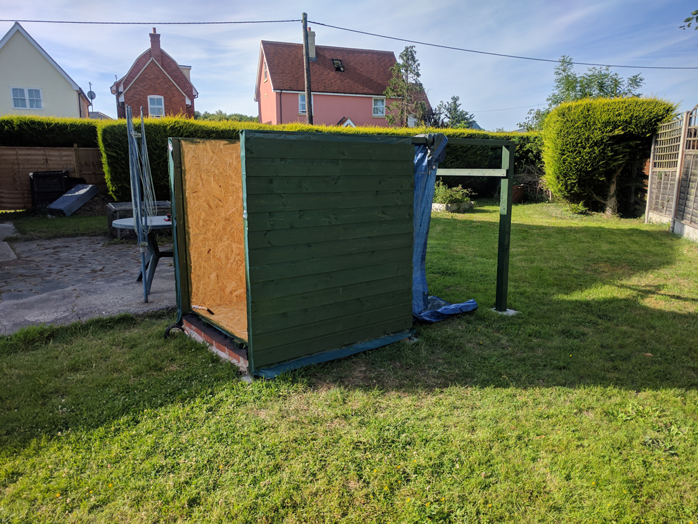
I now proceeded to put up frames for the three plain walls. These were made from lengths of cheap 25 x 50mm roofing batten. The horizontal pieces were attached using small steel corner brackets in such a position as to ensure that the outside face of the vertical piece ends up flush with the outside faces of the fence posts.
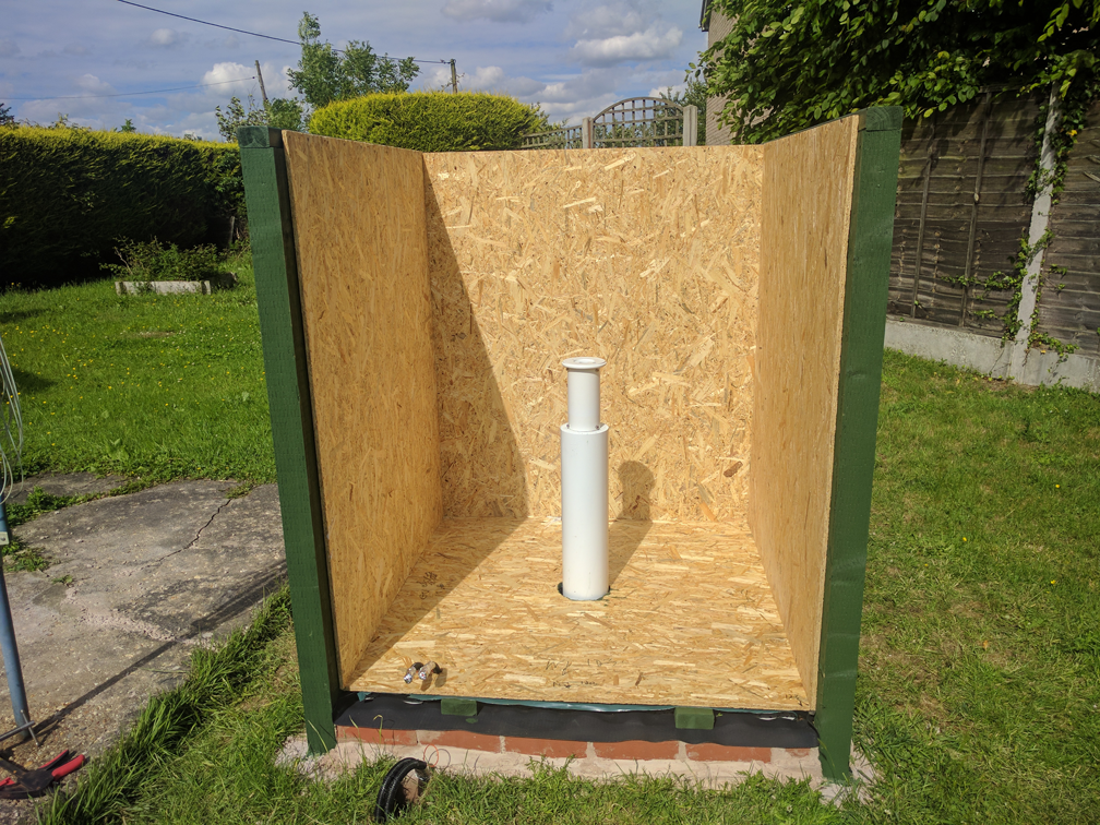
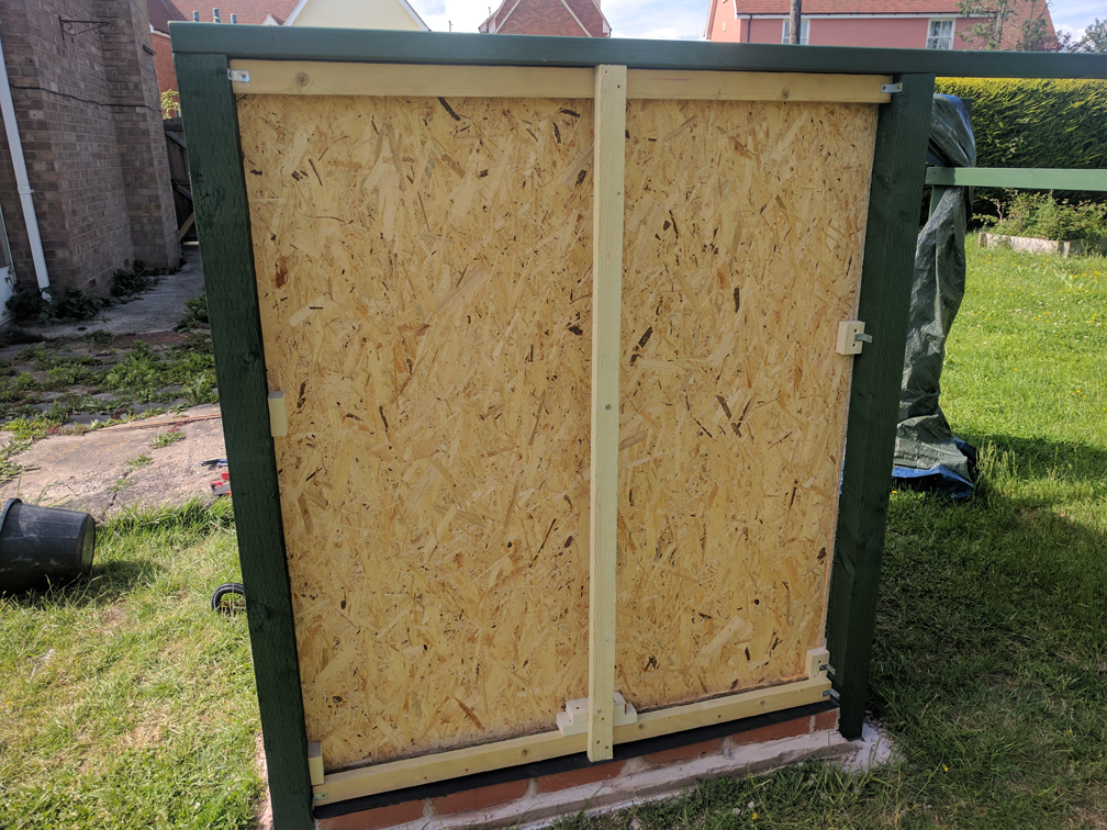
I then cut three more pieces of OSB to make the inner walls. These were fixed in place using blocks cut from roofing batten screwed to the fence posts and wall framing battens as necessary. (I did have to use a couple of corner brackets to help deal with the one slightly misplaced corner post). Again I countersunk the screw heads on the interior side to ensure there was nothing to snag on when blundering about in the dark.
I treated the exposed ends of the OSB with Ducksback as this was the most likely point where moisture would penetrate and cause it to delaminate. I didn’t treat the rear side of the OSB or the roof batten framework as these are completely sealed inside the walls and should not be subject to water ingress (hopefully).
[box type=”alert” style=”rounded” border=”full”]It is important to make the height of the rear wall slightly lower than the height of the front (door side) wall. When building the roof later, a strip of board will be attached to the underside of the roof which presses up against the front wall sealing out the rain. This strip needs to clear the rear wall when opening the roof, which would not be possible if they were of equal heights.[/box]
Insulation and Waterproofing
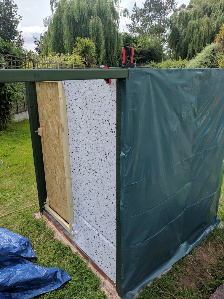
Next I cut pieces of 25mm polystyrene insulation board and fitted them in to the space between the rear of the OSB inners and the outer face of the fence posts and vertical frame. No fixing was required as the polystyrene wedges in quite well if cut exactly to size using a hand saw.
I then cut more vapour barrier membrane and fixed it to the fence posts, roof runners and the bottom frame with a heavy duty stapler. The membrane was cut slightly oversize all round to ensure that it completely enclosed the inner framework and fence posts. Any excess was trimmed at the end of construction to give a tidy appearance.
This is one job where a spare pair of hands would be useful. The vapour barrier is incredibly slippery, much more so than most plastic sheets, and so quite hard to get in to position accurately.
Cladding
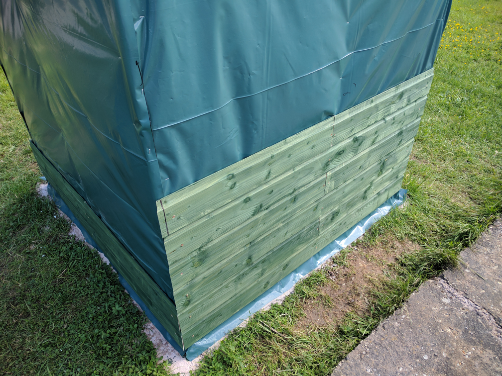
The last step in this part of the process was to fit the pine shiplap cladding. This was probably the single most time-consuming task of the whole build, but if done properly gives a very nice looking and watertight finish. I used 121mm shiplap (12mm thick, with individual strips giving a 109mm face when fitted together).
The same caveats apply as when purchasing timber; if you can select your own shiplap so much the better. Even then, you will have to allow for a fair bit of wastage due to offcuts, splits in the grooves, knot-holes and warped pieces. The shiplap must be fitted so that the grooves are on the bottom edge, which means that the bottom of each strip overhangs the recessed part of the next strip. Water running down the wall will then drip off the edges rather than pooling and making its way to the inside face of the wall.
I treated each strip of shiplap with one coat of Ducksback on both faces, also making sure to work it in to the groove and along the edges of the tongues. I also coated all cut ends as I made them to prolong the life of the cladding.
Each 2,400mm strip was cut in to one long length to complete full run of the wall (approx 1,394mm), and one short length (approx 697mm) to complete half of the next run. I kept the offcuts for later although there was a fair bit of wastage even so. I cut the corner ends of each strip so that they created a 45 degree mitre with the strip on the next wall, but you could just as well cut them square to create a butt joint.
Where two half strips meet in the middle of a wall, I would definitely recommend cutting them so they meet at an angle rather than cutting them square. This helps to keep water out and also allows for a bit of thermal expansion without warping the board.
I fitted one strip all the way around the bottom of the three walls to give me a baseline. This was set so as to overlap the course of engineering bricks by about half the width of the strip. I used a bubble level to ensure the strips were perfectly level all round, as any small error at this stage was likely to multiply as I worked up the wall.
The shiplap was screwed in place with three screws, one in each of the fence post corners and one in the central strip of the framework (or two where the half boards meet). Whilst it might be tempting to put two screws one above another at each fixing point, this would cause the board to split as it naturally dries and warps over time. I also drilled pilot holes and countersunk them to avoid splitting the boards. At this stage, I backed each set of screws out slightly, both so that the next run of boards could be slotted in to place, and also to give the boards time to finish drying out.
I then proceeded to work around adding each new row of boards, fitting them in place and measuring to the posts and framework by eye rather than relying on a ruler so as to get the best fit I could. I also checked each new row with a level and kept tweaking to avoid any error building up. I stopped at around the level of the roof runners, as the final strip would need to be sized once the roof was in place so as to minimise any open gap without fouling the roof.
I gave the fitted boards at least two more coats of ducksback, working it carefully in to all the joints and then allowed everything to dry for about a month before finally tightening up the screws for best fit (again not overtight to allow for thermal expansion and contraction).
The last step was to seal the top of the rear wall by fitting a length of treated timber between the roof runners to act as a cap. As previously noted this was kept a bit below the intended level of the front wall.
That’s it for this post. In the next post we’ll look at building the front wall, door frame and door.