Following on from my post about DIY Nichrome Dew Heater Bands, I’m going to show you how to build a cheap and effective dew heater controller. Whilst preventing dew formation is essential to avoid interruptions to the night’s imaging, we do not want to generate excessive heat as this can cause air currents in front of the telescope’s optics and degrade the quality of the image.
A dew controller enables you to manage the power output of the heater bands, and also helps to conserve battery life if you are away from the mains supply. Commercial dew heater controllers retail for £70 to £100+, but I’ll show you how to make a simple one for as little as £5. Please note that this device is suitable for heater bands at 12V to 24V only.
 |
| DIY Dew Heater Controller |
The basic problem we want to solve is to vary the power output of our heater bands according to the current environmental conditions. As I noted in my previous post, there is no simple way to calculate the correct power output to keep the scope’s optics just above the dew point. What we have to do is use a Feedback Loop to monitor the current conditions and increase or decrease the power output accordingly.
There are two ways in which this can be achieved:
- We could use temperature probes to monitor ambient temperature and the temperature of the optics, plus a micro-controller to adjust the power output of the heater band to keep the optics at a set temperature above ambient. Some commercial dew heaters offer this function (at a premium price), and a number of DIYers have built similar devices using Arduinos and other programmable micro-controllers.
- Adjusting the power output by hand as required. This is the approach I have taken as it is a lot simpler. As an imager I already have too many complicated things to manage and I don’t wish to add to the list. I don’t image in extreme conditions so the temperature tends to stabilise fairly soon after dark. This allows me to determine whether I need to set the heater on low, medium or full power and I rarely have to change the setting thereafter.
If your local conditions are different you may need to be more proactive in monitoring for the signs of dew. Using a dew shield is a good idea as dew will form on the exposed parts of the scope before it starts affecting the optics, thus giving you sufficient warning to crank up the power.
The Theory
If you followed the calculations in my previous post, you’ll probably realise that you could vary the power output of your band in one of two ways:
- By Changing the Input Voltage: Reducing the input voltage results in lower power output from the heater band. The various means by which we might do this are generally less efficient that the method used below.
- By Changing the Circuit’s Resistance: Increasing the total resistance of the circuit also results in lower power output. It would be very simple to insert a Potentiometer or Rheostat in series between the power supply and the heater band, allowing us to adjust the total resistance of the circuit. This is a less than ideal solution as the potentiometer gets hot and also wastes valuable power, a significant issue if you are using a battery.
Fortunately there is a simple solution to the problem, namely to use a PWM controller. PWM controllers (Pulse-width modulation) simply switch the current in a circuit on and off in a regular cycle. By varying the length of the ‘on’ pulses, we can vary the total amount of power output by our circuit. A PWM controller will waste some power, but far less than a potentiometer or rheostat.
Helpfully, the notional voltage of the PWM output is the same as the input voltage, so our previous calculations for heater bands don’t have to be adjusted at all.
Materials
You could build your own PWM controller from components if you enjoy the challenge. Fortunately, the denizens of the DIY Astronomer Forum at Stargazers Lounge put me on to a source of pre-built PWM controllers that are perfect for the job and cost less than sourcing the components required to build my own. (I believe the original idea was picked up from a Dutch astronomy forum though).
 |
| 12V LED Dimmer |
- LED Dimmer, 12-24V, 8A: Search on eBay for these devices. There are lots of sellers and they currently retail for about £2.00 (including postage) from sellers in Hong Kong and China, or about £5.00 from UK sellers. Bear in mind that delivery from HK by surface mail takes three to four weeks. Buy one dimmer for each heater band that you wish to control. Given the long lead time, I bought a few spares in case of failure; others have reported that these cheap devices giving out on them after a while, but mine have been reliable thus far. I also wanted an additional power channel for my LED light box (to be covered in a future post).
- Connection Wire: You will need insulated hook-up wire or speaker wire that can carry the full load that you calculated in the previous article. Generally 1mm – 1.5mm wire should be fine.
For the basic version that’s it! If you want to build a slightly more sophisticated controller, you can obtain the following optional items:
- Plastic Project Box: I bought a project box from my favourite electronics retailer; you just need to make sure you have enough space to hold all of the controller innards (which are much smaller than their own plastic enclosures), plus the connecting wires, etc.
- Red LED and LED Holder: If you are using a 12V power supply, you will need one 12V LED and holder per dimmer. If you are using 5V LEDs or a different supply voltage, use this LED Calculator to identify the correct resistor to put between the power supply and the LED.
- Chassis Fuse Holder and Fuse: In the basic set-up above, I am assuming you have added a fuse in series between the heater band and the controller for safety. In the more sophisticated version, you can add the fuse(s) to the controller box for a neater build. Again you will need one fuse per dimmer, with a rating appropriate to the band to be used.
- Chassis Phono (RCA) Socket: Again you will need one socket per dimmer.
- Power Socket or Power Switch: I salvaged a low voltage barrel-type power socket from a broken piece of equipment to use with my 12V laptop power supply. Alternatively you could wire the power supply directly to a switch installed in the project box.
Equipment
You do not need much equipment for the basic build:
- Wire Cutters/Stripper: This makes life easier, but you could get away with a pen-knife at a push.
For the deluxe build the following are needed:
- Soldering Iron and Lead-Free Solder: For connecting the phono-sockets and fuse-holders. Heat-shrink tube is useful for insulating connections too.
- Drill and drill-bits: For drilling the project box to add the sockets, leds and fuse-holders.
- Multi-meter: This is optional, but helpful for checking connections and diagnosing faults.
- Hot-glue Gun: Useful for attaching the circuit boards to the project box.
Basic Version
The most basic version of the dew controller simply requires you to connect the power supply to the IN terminals of the LED dimmer and the dew heater band to the OUT terminals. Respect the polarity of the IN terminals. The band doesn’t have polarity so connect it either way round.
It is worth noting that the order of the + / – terminals is reversed between the IN and the OUT sides, so take care not to confuse them on the input side. The schematic is shown below:
 |
| Basic Schematic |
You don’t even need to solder any of the connections, merely strip a small amount of insulation from each wire and screw it in to the terminal block. You will note the fuse in-line between the heater band and the controller for safety
It is worth noting that when used with a 12V supply, I have found that my dimmers reach maximum power when the potentiometer is about three-quarters of the way between off and on (the two o-clock position). Power output reduces slightly when turned further towards ‘on’ (but is still nearly at maximum); your mileage may vary.
Making a multi-channel dimmer for several bands would be equally easy. I suggest using the screw-holes to attach each plastic housing to a wooden board (or maybe gluing them in place if that is easier for you). Simply connect each of the IN V+ terminals together using short pieces of wire, and connect each of the IN V- terminals together in the same way. You can then hook up each band to a different pair of OUT terminals.
Deluxe Version
The deluxe version of the dew controller is not much more difficult to build than the basic one. The circuitry is exactly the same, but we will enclose it in a more professional-looking housing that will better withstand life in the field. The build process is as follows:
- Remove the dimmer circuit boards carefully from the original enclosures. First, remove the small screws on the underside of the enclosure and the front part should split easily from the back part.
- Note: The potentiometer is attached to the front part of the enclosure and the circuit board is screwed the the back part. The two are connected by a set of fine wires which are easily broken at the point where they attach to the potentiometer so be careful.
- Pull the black knob off the potentiometer shaft using your fingers. Next hold the potentiometer body (behind the enclosure face) to stop it turning and unscrew the large silver nut at the base of the potentiometer shaft on the front of the enclosure. The potentiometer shaft should now slide out of the enclosure face. Retain the knob and nut for later.
- You can detach the potentiometer from the (usually red) circuit board by pulling the white plug out of the socket at the rear of the circuit board. Again this may avoid breaking the fragile connections to the potentiometer whilst you work.
- Finally remove the small screws holding the circuit board to the back of the enclosure. The circuit board and terminal block should come away in one piece.
Once you have all the parts to hand, decide how you are going to fit them in to your project box. You can see the arrangement I used below:
 |
| Deluxe Version Layout |
- On the right-hand side you can see three dimmer circuit boards (red) with terminal blocks (green) glued in place with hot glue. These are much smaller than their original plastic enclosures (on the right for comparison).
- I drilled a hole to the rear panel of the project box for the black barrel power socket and glued it in place. I attached it to a normal electrical screw terminal block (white, centre) just to make it easy to take things apart if I needed to (you could just run the wires direct to the first set of IN connectors on the dimmer).
- I drilled three holes in the front panel of the project box for the panel phono sockets to the heater bands.
- Finally I drilled the top cover with holes for the potentiometers, holes to contain the panel fuse holders and small holes for the red indicator LEDs. See below for the layout of the top cover.
- On the left-hand side I installed my blue Arduino Uno micro-controller which I am going to use for a future project (so ignore it for this build!)
I then connected everything as described in the basic build above. Here is a schematic for clarity:
 |
| Deluxe Schematic |
- Where I had to connect two wires to one screw terminal (e.g. taking power between IN terminals or adding the LEDS), I soldered the wires together and used heat shrink to insulate. This gave me a more reliable connection, but you could simply screw two wires in to one terminal if you wish.
- Note: Make sure you connect the LEDs the right way round. The long (Anode / Positive) leg of the LED should be connected to the positive side of the circuit. Don’t forget to add an appropriate resistor unless you are using a 12V LED and 12V supply (or a 5V LED and 5V supply).
- I didn’t connect the LEDs as shown due to lack of space when my project box was closed. I actually connected them to the OUT terminal side of the fuse holders. This still indicates the power output level correctly, but it doesn’t give an indication that the fuse has blown. I can live with that but it would have been better to connect the LEDs to the terminals on the phono socket if there had been space.
- Optional: I have put my fuses between the heater bands and the dimmers. If you are concerned about one of the dimmers shorting out you could add an extra fuse between the DC power socket and the dimmers. This would need to have a rating sufficient for combined load of all your heater bands.
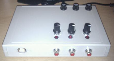
The completed controller is shown below. You can see the LEDs and potentiometers to the front of the project box lid, and the fuse holders at the back. These unscrew and allow me to drop in a replacement fuse easily if one should blow.
 |
| Completed Dew Heater Controller |
Finally I checked everything over with my multi-meter to make sure there were no shorts before closing up the project box and testing with the heater bands. Once I had ascertained where the maximum and minimum points were on the potentiometers, I marked the positions neatly with a permanent marker. There seem to be several variants of the LED dimmer on the market so you will need to check this yourself once built.
The whole project cost me about £25, and the most expensive item was the plastic project box. All in all, making two heater bands and a dew controller I have saved about £120 vs. buying them from a commercial supplier.


Hi,
I have just built something similar and would like to know how you integrated the Arduino board into the control of it, I want to do that with mine but am a complete novice with these boards, I have no idea how to get the Arduino board to control my dew controller, I also used exactly the same dimmers that you did.
Regards
Olly
I haven't done this project, and have no plans to at the moment. The Arduino is one I had from a previous home-made guiding interface for a basic DC motor mount that I no longer use. I am planning to create a stepper motor focuser using the Arduino at some point when I get time.
Here is a link to a mega-thread on using Arduinos for dew-heater control:
http://stargazerslounge.com/topic/162586-arduino-dew-heater-control/
Here is another shorter, more recent one:
http://stargazerslounge.com/topic/225528-arduino-dew-controller-feature-rich/
HI
i am currently buying the components to make the larger box version of the dew heater for my obsy. One question though – as i plan (as you have) to put a fuse in per dimmer, what amp fuse should i use? As each dew band should not be outputting more than 0.8 amps, should i use 1 amp fuse? i think you can get 1.25 and 1.5 amp too. i guess i am asking what amount of Torrance i should give my dew heaters.
thanks
Andy
If you know you will not exceed 0.8A then a 1AA fuse should work, but 1.25A would give you a bit of headroom. There is no real downside to having the lower fuse rating to start with, provided you have a spare in case it does blow. Go too high and you could have problems with overheating in case of a short, so dont use a 13A or similar.
This is a great project and really simple, thanks for sharing.
Does the 12V power supply neede to have a certain power output?
Read my other article about making heater bands for details of how to calculate the current draw of a band (or set of bands). If you have purchased commercial ones, the documentation may tell you, or failing that measure the resistance and plug the figures in to the spreadsheet linked to in the article:
http://www.blackwaterskies.co.uk/2013/05/making-your-own-nichrome-dew-heater.html
I just built a control box using the exact same dimmer. I'm only able to get 12.2 -12.6 v variability. Is it supposed to be more?
No. The output voltage should be pretty much the same as the input voltage, so if you're putting in somewhere between 12-13V, you should be getting 12-13V out.
The variation in power is due to Pulse Width Modulation (PWM). Basically the dimmer control switches the current on and off rapidly and repeatedly. As you turn the dimmer to the lower power setting, the circuit spends more time in the off state than on, whereas turning it up means the opposite happens.
This power cycling is the best way to dim an LED light source as LEDs will only operate in a fairly narrow range of voltages. Drop the voltage too much and the LED goes out rather than dimming, push it too high and it will burn out. By switching the LED on and off rapidly (faster than you can detect by eye), it appears dimmer to the human eye due to persistence of vision, but to something like a fly's vision it would appear to be flickering on and off.
A dew heater band will work at a wide range of voltages though, so we could simply reduce the voltage using a potentiometer or other arrangement of resistors to cut the power. That's pretty inefficient though as you're just turning the excess power to heat in the resistor, wheras PWM is much more efficient (and the calculations are easier) since the voltage remains constant but the power cycles on and off.
Due to the rapid cycling, your multi-meter will show an output voltage close to the input voltage. If you used an oscilloscope to measure the output, you'd see a regular cycle of pulses where the voltage rises from 0V to 12V and back to 0V again.
That makes sense then. Thank you for providing the information and allowing myself to become more educated. I ended up using 16.1 ohm per m through 16v, to achieve 0.27 w per cm on my 75 cm band. At 18v it works out to 0.36w per cm. Tested on the sct today and works great. Thanks again
wondering.. what say you about a 3 channel dimmer? looks like 3a per channel… to run 50mm guide scope. 80mm scope. and lazar for alignment of scope to sky… thats only a few mins of time..
i can post link if wish.. to see what iam askin about..
thank you for any help on this…
Phil
Hey,
I have a question, based on your deluxe diagram, it appears that the LED hookup closes the circuit loop, so even if you don't plug in a heater, all lights with be lit (as long as a power is supplied).
If i'm reading that correctly, then, how would you be able to hook up the LED, so that it turns on only when a heater strap is connected?
You are correct that the LED will always be "On" in this design. The LED gets brighter or dimmer depending on the setting of the controller, so you can figure out (roughly) how much heat is going to be generated. I just turn down the controllers on any unused channels. If you want to do something more sophisticated, perhaps take a look at current sensing circuits, the output of which can be used to drive an LED and would likely do what you want. Try here for example: http://cds.linear.com/docs/en/application-note/an105fa.pdf
Thank you so much for this guide.
So far I have successfully made the control box and an eyepiece heater band, your easy to follow guides made it a doddle.
Tomorrow’s project is the OTA heater band!
Great article and simple to follow. However, I wondering why the fuses were on the negative as opposed to positive side of the circuit?
In an AC circuit you must put the fuse on the live wire since that’s where the current originates from, the other side being ground with no current until the circuit is completed. In this DC circuit the potential is low and there is no connection to ground, so it makes no real difference which side you fuse. If you’re happier putting the fuse on the positive side then it will work fine and it is more conventional.
Thanks Ian,
One thing I have noticed is that when I turn up one pwm, it appears that all of the LEDs come on and there is no dimming in brightness on any of them with movement of pwm so cannot indicate how much power. I have built the project in a metal box and am certain there are no shorts between case and positive side of circuit. Is this normal or have I made a fundamental error?
I’m having the same issue, when I connect them independently it works fine. But when I connect 2 as shown in the deluxe diagram both led’s come on full power and there is no adjustment when turning the pot. This is a 2 configuration and not 3 as in this article but it shouldn’t matter. These are actual PWM’s and not “Dimmers” as used in this article.
If you’ve wired the circuits correctly there is no physical way this could happen, and I can only think you’ve got the input and output sides of the dimmers/pwms mixed up or crossed over somewhere. The input sides of each dimmer are wired in parallel to the power supply, so turning one up or down should have no effect on the input to the other dimmers. The only possibility is perhaps the load attached to the output side is exceeding the power available from the supply. You can check that by disconnecting your dew heater bands from all the dimmers and just checking the LED operation. If the LEDs dim individually with no load, look at how much power each band is drawing relative to that available supply.
If you still have a problem with no load attached, then the only explanations are either:
a) Your wiring is wrong, or perhaps at an outside chance the terminals aren’t labelled properly which is always a possibility with cheap components from China. The output side of each dimmer is independent of the other dimmers, and again adjusting one up or down cannot have any effect on the output from the others assuming you’ve ruled out problems with the load as set out above.
b) The dimmers/pwms are faulty somehow or you’ve bought a component that isn’t what we’re using here. I know a lot of the cheap dimmers don’t perform brilliantly in that there isn’t a linear change in duty cycle relative to the adjustment range on the potentiometer. It may come to full power very early in the range, or conversely only start increasing power very late in the range. That’s just a result of cheap components being used in not very well designed circuits, and other builders have certainly modified certain components on the dimmer PCB to give a more linear result. I’ve not found the need to do so myself, but regardless I cannot see such an issue affecting other dimmers as you both describe unless there is something seriously wrong with the batch you have bought? If a single dimmer performs as expected, there should be no reason why several wired in parallel would have the issues you describe.
Sorry I can’t be of more help but this isn’t something I’ve seen before.
Thank you Ian, I’ve purchased the same exact dimmers in as in this article. Same issue, I’ve connected + from the power supply to + on the first dimmer. Jumped that to the + on the second dimmer. Connected – to the first dimmer and jumped that to – on the second dimmer. Pretty simple. Still have the same issue. If I turn up one, up the other goes up as well. I’ve triple checked the wiring and it’s correct and I’ve checked with no load.I simply don’t understand why it does this but it does it with both units I’ve tried. The power supply has 12v output but it’s also a “switching” power supply. Could that make a difference? The markings on the dimmers are exactly the same as yours in this article. I really appreciate your input on this.
Thank you so much for that. Several years ago, I made a 4-channel version (lesson learned long ago: allow for kit expansion) and it has served me well ever since. The only “blip” was that one of the PWM controllers failed after a couple of uses – fortunately, I had bought six to allow for user-incompetence, so I was up and running again in no time.
I am now shamelessly borrowing (and tweaking) ideas from your observatory build. Again, thank you – you provide a great service to the DIY-astro community.