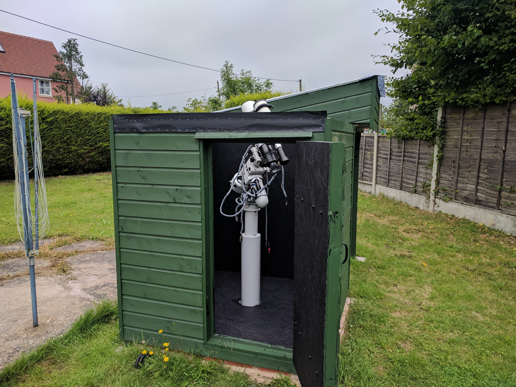
In this series of posts, I’ll set out details of how I built a small roll-off roof back garden observatory for my imaging equipment. I’m by no means an expert DIYer, though I do tackle smaller jobs around the house when the mood strikes. Building with wood is not as daunting as it might seem. It is largely a matter of common sense and most problems can be overcome with a bit of perseverance.
This project took me four and a bit months from start to finish, working about four half days per week on average. The total cost in materials was less than £1,000 (UK pounds), and most of that went on wood and sheet materials. Full plans and lots of photographs of work in progress are provided below.
Size Requirements
As noted in one of my earlier posts (Observatory Planning and German Equatorial Mounts), my objective was to build a small observatory to be used for remote control imaging; picture my scope and camera out in the cold and me on the sofa in the warm and you get the idea! The observatory needed to accommodate my Skywatcher NEQ6 mount plus Skywatcher ED80 scope, Orion ST80 guide scope plus cameras and filter wheel. I am certain that any future imaging scopes I might want will be shorter than my current set-up, so did not feel the need to make the observatory any larger.
Using the method described in my previous post, I calculated that the internal size of the observatory should be 1.22 x 1.22 metres (including a small margin for error). Bear in mind that this leaves no space for an observer; the clearance is minimal but sufficient to avoid any collisions between equipment and walls. Limited space can make setting up and adjusting equipment somewhat challenging, but during normal operation it is not an issue as everything is computer controlled and operated remotely. Keeping things small meant that material costs were reduced and most of the work could be undertaken solo apart from the occasional “You nod your head and I’ll hit it!” moment. Lifting the partially complete roof on was a one man and a boy effort and could probably have been accomplished unaided if needed.
The intersection of the RA and DEC axes of the NEQ6 mount was set to be approximately 1 metre above the final floor level of the observatory. This is far too low for visual use, but advantageous for imaging as the pier is relatively short. This reduces flexure at the scope end and thus avoids the need for an excessively large foundation block or a very thick pier.
The main challenge of such a short pier is viewing through the NEQ6 polar scope. I overcame this partly by positioning the observatory door to the South of the pier so that my legs could poke out of the open door when looking through it, and more importantly using software (Sharpcap’s polar alignment tool) to fine tune the mount’s polar alignment.
The other necessary compromise was that, due to the close proximity of the walls, they had to be kept as short as possible. I don’t have open horizons but even so I did not want to lose access to parts of the sky unnecessarily. As a result the scope can protrude in to the path of the roll-off roof, and so must be parked in to a custom position below the wall line before closing the roof. This is not a problem at the moment as the roof is opened and closed by hand, but would present a risk if using a remotely controlled motorised roof.
Location and Planning

There were a number of possible options for siting the observatory within the garden, and I spent a fair bit of time considering the best choice. There are no street lights in our area, but I did try to avoid locations where lights from nearby houses (including my own) would affect imaging. I also looked for the best access to the sky considering roof lines, trees, etc.
I sited the observatory so that is is easily visible from the house for security, but not in an obtrusive position. Most importantly, I ensured that I had a view of Polaris to enable easier polar alignment. This can be overcome if there is no other option, but why make life harder than necessary?
I spent a few weeks drawing reasonably accurate plans, as it is a lot easier and cheaper to fix problems on the computer. Even so, some changes proved necessary as the build progressed. I also satisfied myself that the proposed structure would not require planning consent; I offer no advice in this regard as it very much depends on the location of your property, the location, size and construction of the observatory and any other permitted development you have previously undertaken.

I have updated the plans to reflect the “as built” situation as far as possible and they are available here:
Having determined the size and position of the observatory, I built a mock-up of the outer shell using bamboo canes, string and cable ties. This was a useful exercise and it gave a much better feel for the reality of the project than lines on paper.
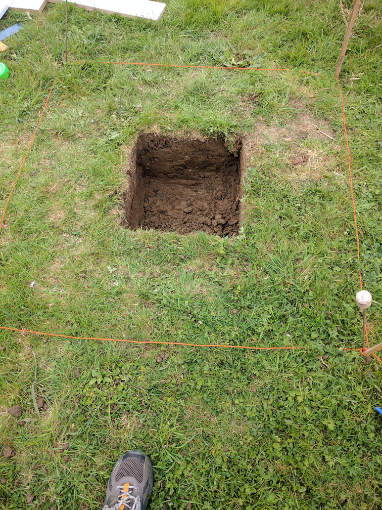
Satisfied with the position and size, I marked out the footprint of the observatory and the centre point of the pier using orange twine and canes. It is worth taking a fair bit of time over this. To ensure everything is square, the diagonals between corners should be of equal length.
Despite my best efforts, the corner posts of the observatory ended up being out of true by a couple of centimetres on one side vs. the other. As noted previously, working with wood it is easy enough to overcome minor setbacks like this. Do your best to keep things square and level as it will make life easier, but don’t despair if you fail to reach perfection.
[box type=”alert” style=”rounded” border=”full”]All measurements are in metres and the plans are to scale if printed on A4 paper. I make no representations as to the accuracy of the plans or the usability or safety of the final structure.You use them at your own risk.[/box]
Digging the Pier Foundation
Having found the location of the centre of the pier, I dug a square hole for the foundation block. It is important that the pier foundation is isolated to avoid vibrations being transferred to the scope. This is far less of an issue when imaging remotely than for visual observing, but still worth bearing in mind. Therefore the pier foundation and pier are not connected to any other part of the structure.
The vexed question of how large the foundation block should be now had to be addressed. There is no right or wrong answer to this as it depends on the local climate and the ground conditions. In the East of England, we are blessed with a relatively benign climate and not subject to excesses of heat or frost. The frost-line is pretty shallow and so foundations do not need to be excessively deep to avoid frost-heave.
On the other hand I was building in heavy London Clay. The ‘soil’ is saturated with water in the winter, and tends to dry out to a concrete-like consistency, crack and shrink during a dry summer. This may give rise to some movement of the foundation over time, but on the plus side the ground is heavy, extremely well compacted and is not ‘made up ground’. I left the pier foundation hole to dry and shrink for a couple of weeks whilst I completed the plans and purchased materials.
The pier that needs to be supported is also relatively short and thus the turning moment exerted on the foundation is correspondingly lower than a visual observing pier would be. Ultimately I decided to dig a hole 0.45m x 0.45m x 0.45m. This is smaller than the 1 cubic metre foundation often cited, but I have yet to see any sound engineering advice as to why such a large foundation is necessary other than ‘Just in case!”.
I am fairly confident that the foundation will not move significantly over its expected life. The combined weight of the concrete in the foundation, pier and shallow observatory foundations is well in excess of 600 KG. I’m absolutely confident that my back was not capable of digging or mixing more than it did! In the photograph the hole looks quite small, but in practice it produced six or seven barrow loads of extremely heavy clay!
Making the Pier Head

The pier itself is made from concrete in a steel tube. To connect the NEQ6 mount head to the top of the pier, I obtained and off-the-shelf Skywatcher NEQ6 tripod extension. These are designed to sit between the top of the NEQ6 tripod and the base of the mount head, making it easier to use long refractors and Newtonians without them colliding with the tripod legs.
The extension consists of three parts; a black-anodised aluminium base disk, machined to fit the top of the tripod, a white alloy header disk machined to fit the bottom of the mount head and a steel tube joining the two by means of two sets of three hex-cap machine screws. Modifying the extension to act as a pier head is relatively simple and a good option unless you have access to a friendly machinist or you are willing to pay the fairly outrageous prices for off-the-shelf pier head adaptors.
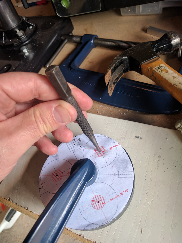
The modification consists of drilling 3 M12 holes through the black anodised disk. A 1:1 template is provided in the plans for this purpose:
Print the template on A4 paper, cut out and stick it to the flat side of the black anodised disk and then mark the centres of the holes using a centre punch and hammer.
[box type=”alert” style=”rounded” border=”full”]The three screw holes for the hex-cap machine screws around the sides of the disk are marked on the template. Make sure you align the template with these. If you drill the new M12 holes through the existing screw holes you will render the extension useless! It is also important to make sure the new holes are correctly positioned so that the pier head can be aligned to North as described later.[/box]
I used a cheap “Titan” drill press for this job; it’s not the best but still more accurate than trying to use a hand-drill. I set the drill press to the recommended speed for soft aluminium as per the instructions and drilled a pilot hole with a small HSS drill bit. I then reamed it out using an M12 HSS drill bit. It is important to keep the drill bit lubricated (I used cutting paste and WD40) proceeding slowly a small amount at a time and clearing the hole of metal chips regularly. Bear in mind that if you let the drill bit overheat, you will blunt it quickly and have to sharpen it or get a new one. Make sure you wear suitable eye and hand-protection as chunks of hot metal and sharp swarf will be flying around.
[box type=”info” style=”rounded” border=”full”]The placement, size and angle of the holes is not going to be great with a low-end drill press like this and even worse with a hand drill. It doesn’t do any harm to make the new holes slightly oversized to provide some wiggle-room. Furthermore, when setting the stainless steel studding in the concrete pier head, ensure that the black anodised disk is used to hold them in the actual positions you have drilled, rather than the theoretical positions marked on the plan. One of my holes was out by at least a millimetre and it would have been impossible to fit the disc over the studs if I hadn’t done so.[/box]
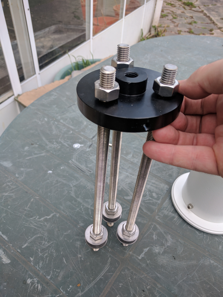

Next you will need three lengths of M12 stainless steel studding plus fifteen M12 stainless steel nuts and twelve or fifteen M12 stainless steel washers with a diameter of no more than 35mm (slightly smaller is OK but larger will not fit inside the extension tube). All of these items are readily available online, try eBay or Amazon for example.
Thread the studs through the new holes in the black disk, making sure the boss in the centre of the disk is pointing ‘upwards’; this is upside down compared to how it would be used on a tripod but we want the flat face of the disk to mate with the top of the pier. You will need to have enough studding protruding up to fit one of the washers plus two of the nuts.
At the other end of the each stud, thread on a nut, then a washer, then a nut, another washer and a final nut. These extra nuts and washers will help to anchor the studs in the concrete later. Some people make an L-bend in the end of each stud using a vice to prevent it twisting in the concrete. I didn’t due to the limited clearance inside the pier, and (provided the fastening nuts aren’t over-tightened by the Incredible Hulk) there is no issue.
Finally, re-assemble the whole extension. Identify the two holes in the top of the white disc. The azimuth adjuster pillar is removed from the tripod head and screwed in to the hole directly above the stainless stud (not the hole above the gap between the other two studs). Refer to the instructions that came with the pier extension for details.
The line between the two holes on top of the extension must be aligned North-South when you set the stainless studding in the concrete pier, with the azimuth adjuster hole to the North side. There are no second chances with this one so read the rest of this post to make sure you understand how the mount, extension and pier need to align to North before you pour the concrete!
A Hole Lot More Fun

Having let the pier foundation hole dry out for a while so that any (local) shrinkage took place, I made a square and level head around the top of the hole. I did this by wideneing the top of the hole to the depth and width of one engineering brick all around.
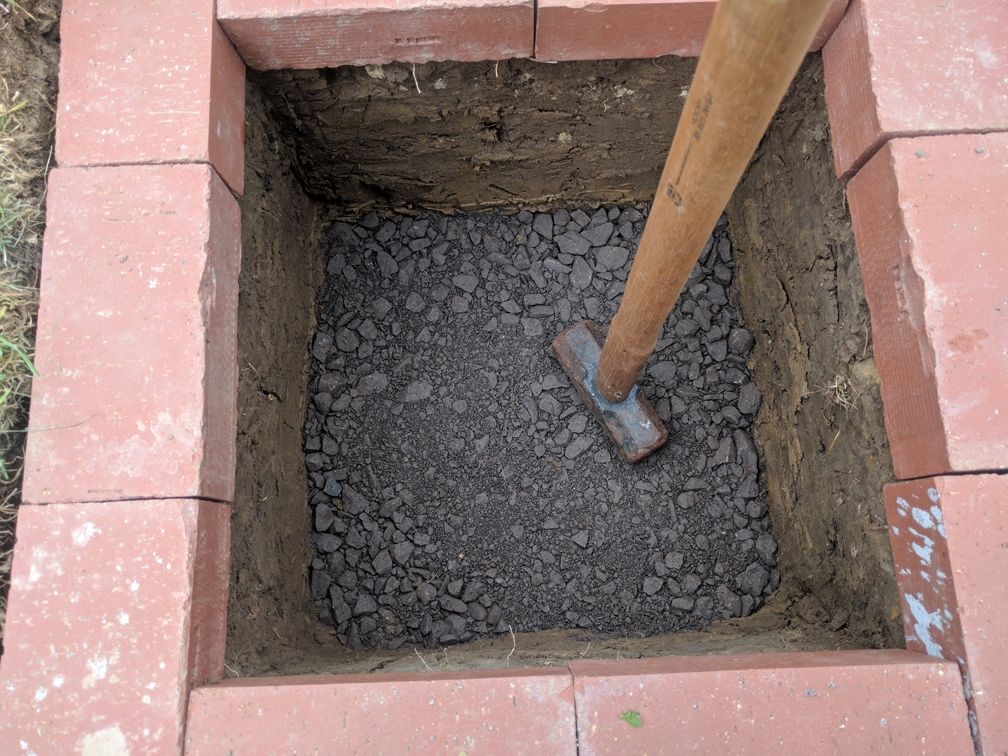
I then laid the bricks dry on to the soil so that they slightly overhung the main hole (by a centimetre or two) and packed and levelled them using handfuls of sub-base material. The head is not structural and is just there to stop the (by now) dry clay from crumbling away from the concrete foundation and to give the final level for the concrete itself.
Next I put a few centimetres of sub-base in to the bottom of the foundation hole and tamped it down firmly and as level as I could make it. This supports the concrete whilst it cures.

The next step was to position the 10mm reinforcing bar (rebar). I obtained five x 1 metre lengths of this from eBay for a reasonable price. I cut two of the lengths in half and hammered these a short way in to the sub-base and soil near the corners of the hole. As I was planning to pour the foundation in two halves, this was necessary to tie them together with rebar; pouring wet concrete on to dry concrete does not form a strong bond.
Next, using the “Rebar and Studding Template” contained in the plans, I made a wooden template out of some old chipboard (you could use plywood or MDF just as well). I drilled three M12 holes corresponding to the positions of the holes in the black-anodised extension base, remembering to match them to the actual hole positions I had achieved rather than the theoretical positions on the plan. I then drilled three M10 holes for the rebar following the template.
The template ensures that the rebar and the stainless studding do not collide when fixing the latter in to the concrete pier.
Finding North

When positioning the rebar, it is essential that the wooden template is aligned to North as per the North marker printed in the centre of the paper template. To get a clearer picture, it might be a good idea to temporarily fix the pier extension (with the azimuth adjuster pillar screwed in place) to the wooden template using the studs and bolts. The azimuth adjuster pillar must on the North side of the hole.
Orientation is not absolutely critical at this stage since we’re just trying to ensure the rebar does not obstruct us from accurately orientating the pier head when we set it in concrete. There is plenty of space for this, but you do not want to end up with a piece of rebar sitting where you want a stainless stud to go!
Find the centre of the foundation hole by measuring halfway across the two diagonals and mark that position. I used some powdered chalk to do this but a small wooden peg would also work. You need to be as close to the centre as possible, because if the pier ends up being offset a long way your equipment may collide with the observatory walls. From the centre point, you need to find and mark out the line to due North.

The sure fire way to do this is to wait until Polaris is visible in the evening and sight along a line fixed at two points at the edge of the hole and some way North of it. Failing that, you can use a decent magnetic compass to find magnetic North and correct for your local magnetic declination to find true North.
Fixing the Rebar
Finally remove the extension tube from the wooden template, having worked out which side is the top and which side is North. Position the template in the hole over the centre mark and properly aligned to the North-South line. Take the remaining 3 lengths of 1 metre rebar and hammer them a short way through the sub-base and in to the ground using the 10mm holes in the template as a guide. You should end up with a triangle of rebar pointing due South as shown in the pictures above.
Don’t go mad hammering the rebar, you want the top of the rebar to overlap the bottom of the stainless studs when the pier is assembled. That’s it for this post; in the next one we’ll be getting messy with concrete and finishing off the pier.