When astro-imaging, taking flat frames is essential to calibrate your images. A flat frame is just an image of a uniformly illuminated, featureless surface that essentially creates a “map” of how light travels through the telescope, filters and camera. When processing the images, the light frames (i.e. images of the night sky) are divided by the flat frame. This corrects for any differences in illumination caused by vignetting (drop off in brightness at the edges and corners of the image), shadows caused by dust on the sensor and differences in the response of individual camera pixels to incoming light.
Flat frames can be made by taking images of the twilight or dawn sky and processing them properly, but the most convenient method is to use a light box or flat panel as the source of illumination. A manual light box or panel is easy to make using foam board and white LEDs, but must be placed on the end of the telescope each time it is to be used. Commercially made light boxes that can be remote controlled by imaging software such as Sequence Generator Pro are available but cost anywhere from £170 and upwards depending on size and features.
In this post, I’ll explain how to build a remote controllable flat panel for less than £25 that will enable you to automate another aspect of your observatory without breaking the bank.
Parts List
The parts list for this build is relatively short:
-

LED Tracing Panel LED Tracing Pad: The most important element of this build is an LED tracing pad. These are readily available from Amazon and other retailers, but do vary significantly in quality which makes it hard to recommend an exact model. The key features to consider are:
- The panel should be powered via USB (i.e. 5 volts). Whilst it is entirely possible to use a panel powered by its own 12 volt power supply, it is beyond the scope of this post to explain the differences in wiring, etc.
- The panel should be dimmable. Typically panels offer 3 (or more) levels of brightness controlled by a touch-sensitive button. This ensures that our controller can adjust the brightness to suit different filters as required.
- The panel should provide even illumination across the entire surface. LED tracing panels tend to be constructed in one of three ways. Some have a grid of white LEDs arranged behind a diffuser screen. This type is not generally suitable as there will be brighter and dimmer spots across the whole panel. The next have a strip of LEDs along one edge – these tend to create gradients from one side of the panel to the other. The best type have two strips of LEDs (often 60 in total) arranged along two edges of a transparent acrylic sheet sandwiched between a layer of white reflective material and white diffusing material. The illumination of this latter type tends be much more even.
- The panel should be large enough for your scope’s diameter; an A4 tracing pad is fine for an 80mm refractor, but you may need an A3 model for a larger telescope.
- The panel I used was £15 from Amazon but since models come and go quickly, you will need to read the reviews to ascertain the quality of illumination.

-

Arduino Nano Clone Arduino Nano (or compatible clone): The Arduino Nano is a microcontroller board that will provide the interface between the computer and the LED tracing pad. You don’t have to use a Nano, any Arduino board that meets the following specifications will do:
- The board must be a 5 volt board powered via the USB port. Whilst you could use a different board, it is beyond the scope of this post to explain how to change wiring and power supplies for 3.3V and 12V Arduino board and clones. Note that many Arduino boards come in both 5V (16MHz) and 3.3V (8MHz) variants, and it is the former you require.
- The board should be based on the Atmel 328 microcontroller, often described as an ATMega328, ATmega328P, etc. Important: Avoid using Atmega32u4 boards such as the Arduino Leonardo or the Pro Micro boards. The problem with 32u4 boards is that the computer software must set and control DTR and RTS in order to communicate with the board. Imaging software such as Sequence Generator Pro does not do this, and won’t be able to talk to the microcontroller.
- I used this £5 Arduino Nano board from eBay. It has a micro USB connector, but note that official Arduino Nano board and most clones have a mini USB connector instead. Either type is fine, just make sure you have the right sort of USB cable to hook it up.

-

IRF520 N MOSFET IRF520 N Channel MOSFET: This is a small electronic component that switches the power to the LED panel on and off in response to signals from the Arduino Nano:
- These are readily available and cheap. The one I purchased was slightly less than £2 from eBay.
- Note that this is an N Channel MOSFET which is suitable for the polarity of my wiring scheme. The other type of MOSFET is the P Channel type which won’t work here.

- USB Cable: You will need a USB cable long enough to connect your computer to the Arduino Nano:
- Ensure that the cable provides both data and power; the USB cable supplied with the LED tracing board will typically be a charging (power-only) cable, so if you find you cannot communicate with the Arduino Nano that would be the first thing to check.
- Also ensure that the connector is the right type for your board (typically USB A to USB Mini or USB A to USB Micro).
Preparing The LED Panel
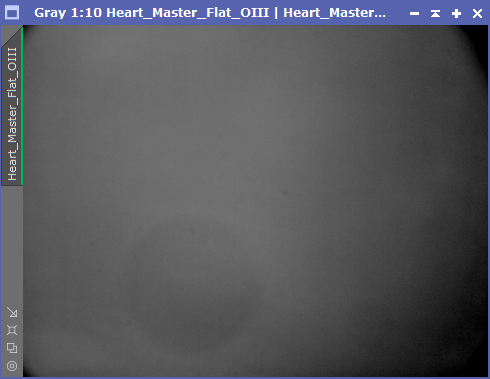
Firstly test the LED tracing panel by plugging it in and examining it visually to see if the illumination is obviously uneven. Before proceeding further I’d also recommend taking some flat frames using the panel and your telescope and camera. You may need to adjust the brightness of the panel or even dim it further by placing one or more sheets of white paper between the panel and telescope. A good method to test the panel is to take a flat frame, rotate the panel 90 degrees relative to the telescope and take a second flat frame. Now calibrate the first flat frame (treating it as if it was a light frame) using the second flat frame in your favoured image processing software.
Stretch and check the resulting calibrated frame, looking for any banding, gradients or uneven illumination. If the panel creates a nice even field, you should end up with an image that is a single tone of grey or white across its entire area. Any differences across the frame will either be due to poor flats technique (beyond the scope of the this post to explain) or a panel that is not evenly illuminated. If the results are unacceptable, this is your opportunity to return the panel for a refund and try a different model.
Note: These USB tracing panels don’t appear to draw much current, but if yours doesn’t illuminate you may not have sufficient power available from that USB port. Certainly test the panel using whatever USB port you intend to use in your observatory. If you’re using a USB hub, you’ll probably need one that takes an external power supply in order to provide sufficient current to drive the LEDs. If plugging directly in to your computer, be aware that blue (USB3) ports provide more current than standard black (USB2) ports, and orange (USB3 charging ports) provide even more.
Assuming you’re happy with the panel and willing to invalidate your warranty, next you will need to perform some surgery on the panel.
-

LED Panel Control Board Identify the corner where the panel’s USB port is. With the panel turned on you may even be able to see the circuit board inside the panel. You will need to peel back the rear cover of the panel just in this corner; it will most likely be glued to the rest of the panel, so slide a thin screwdriver or blade between the backing and the panel and gently lever upwards. The rear cover should peel away exposing the innards. There is no need to remove the entire backing, just peel it back so you can access the circuit board and use something to prop up the peeled corner so you can work.
- You should see a circuit board similar to the one in the photo. You need to identify the leads going from the circuit board to the LED strips – in this case it’s obvious they are the grey and white wires soldered to the board where it says ‘LED’!
- Next you will need to plug in the USB port, switch on the panel and then use a mutli-meter to check the two wires to see which is positive (+5 volts) and which is ground (GND). Set the multi-meter to the 20 volt DC setting and put the probes on the two solder pads and check the reading. If you get somewhere around +4 to +6 volts, the red (positive) probe is touching the positive (+5 volt) wire). If you get a negative voltage reading, just reverse the probes. In my case the grey wire proved to be the positive terminal, and the white wire was ground. Make a note of your findings.
-

LED Wires and Backing Unplug the panel before proceeding. Next you will need to desolder the wires to the LED strips from the control board. Use a soldering iron to heat each of the two solder pads in turn and pull the wire away using tweezers. If there is a lot of solder you may need to use a desoldering pump and/or desoldering braid to detach the wires.
- Next, cut a small notch out of the panel’s backing surface to feed the now detached wires through. You can then stick the backing panel down again with the wires protruding. The original control board will no longer play any part in operating the panel.
Building The Controller
Test your Arduino Nano or whichever microcontroller board you have purchased. You will need to install the Ardunio IDE, connect the board and test it (e.g. using the Blink Sketch). It is beyond the scope of this post to explain troubleshooting or testing Arduinos. There are vast numbers of resources online on the subject, but a few things to check:
- Make sure you select the correct board model in the Arduino IDE (under the ‘Tools’ menu). In our case we want the ‘Arduino Nano’.
- Select the correct COM port for the board once you have plugged it in, (again under the ‘Tools’ menu).
- If you are using a Nano, you will also need to select the correct processor (under the ‘Tools’ menu). This will either be the ‘ATmega328p’ or the ‘ATmega328p (Old Bootloader)’. If you find you are unable to upload a sketch to the Nano successfully, try the other option. This setting does not apply to other Arduino boards, only the Nano.


Now we need to do a bit more soldering to create the following circuit:
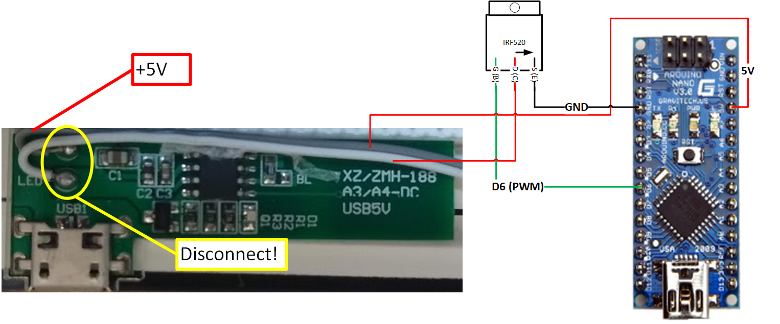
- Identify the +5V wire to the LED strips which we found above. In my case it was the grey wire. This needs to be soldered to the +5V pad on the Arduino Nano. If you are using a different microcontroller, you may need to connect to the ‘RAW’ pad instead. Provided you are using a 5V board powered by USB, the 5V or RAW pin will be outputting +5 volts with sufficient current to run the LEDs.
- Next take the IRF520 MOSFET and look at it from the front; the rear of the MOSFET will usually have a metal tag and surface. You need to identify the leftmost of the three legs on the MOSFET, the Gate (or G) leg. This needs to be soldered to pad D6 on the Nano. I used a short length of thin wire soldered directly between the MOSFET leg and the Nano. Again, if you are using a different microcontroller, you need to ensure the Gate leg is attached to any pin which is capable of PWM output (check the specifications for your board, typically 5 or 6 of the digital outputs will support PWM).
- Now attach the right leg of the MOSFET, the Source (or S) leg, to one of the GND (ground) pads on the Arduino. There will be two or three GND pads on most microcontrollers, use whichever is most convenient.
- Finally attach the second (GND) lead from the LED strips to the middle leg of the MOSFET, the Drain (or D) leg. In my case this is the white wire that we identified earlier.
- Check that you haven’t created any solder bridges between pads on the Arduino board and that none of the wires is short-circuiting with other wires or the legs of the MOSFET!
You should end up with something that looks like this:

Note that the positioning of the wires is a bit unclear in my photo – the white wire is definitely attached to the middle leg of the MOSFET even though it looks otherwise. Once you are happy with your wiring and soldering, plug the Arduino’s USB port in to your computer USB port, again being aware that it needs to provide sufficient power to drive the LED strips as identified in testing above. Hopefully there will be no sparks or magic smoke, and the small LEDs on the Nano should illuminate as they did before. If not, double check your connections for short circuits; it is possible to fry the Nano in some circumstances but they’re fairly robust usually.
What’s Going On?
The purpose of the circuit we have built is to switch the LED panel on and off and to control its brightness. The Arduino can output sufficient current at +5V to illuminate the LEDs via its +5V or RAW pin, but this is always ‘on’ when the Arduino is plugged in to the USB port which isn’t much use. The controllable output pins (D1 through D12 or similar) can be switched on and off by the microcontroller at will, but can only output a very small amount of current which is insufficient to illuminate the LEDs.
So what we do is use the MOSFET as a switch. We feed the large current from the +5V or RAW pin on the Arduino to the LED strip via its +5V wire. We then feed the returning GND wire from the LEDs in to the Drain pin on the MOSFET, allowing the current to flow in to the MOSFET and then back out of the Source pin and on to the GND pin of the Arduino thus completing the circuit. The clever bit is that we attach one of the low current digital (D) pins on the Arduino to the Gate pin of the MOSFET. When the Arduino D pin is off, the Gate pin is also off and no current flows through the Source to Drain pins. As soon as switch on the Arduino D pin, the small amount of current it provides switches on the MOSFET and allows the much larger current to flow through the LEDs and MOSFET.
Importantly we don’t use just any old Digital (D) pin on the Arduino to switch the MOSFET on and off. We must use on of the pins that allows PWM output. PWM stands for Pulse Width Modulation, and effectively the output from the pin cycles on and off rapidly. We can set the PWM cycle to be 0; off all the time, 128; on 50% of the time, 255; on 100% of the time or any value in between. The rapid switching on and off causes the LEDs to switch on and off rapidly which to our eyes (and the camera) appears to be dimming the LEDs. Thus we have modified our LED panel from its original 3 levels of brightness to 255 levels of brightness! In my case I have used pin D6 which is one of several PWM capable pins on the Nano.
In order for all this to work of course, we need to program the microcontroller to control the LEDs and to talk to our image capture software.
Programming and Testing
The Alnitak flat panels are controlled using a simple command specification sent via the serial port. The specification is here:
https://www.optecinc.com/astronomy/catalog/alnitak/resources/Alnitak_GenericCommandsR4.pdf
In order to make our flat panel respond to these commands, we need to program it. Open up the Arduino IDE and ensure that it can still talk to your Nano or other board. ‘Tools -> Get Board Info’ will return a small amount of information about the board if it is working:
- Create a new sketch in the IDE and then:
- If you plan on using Sequence Generator Pro, go to this link: https://github.com/jwellman80/ArduinoLightbox/blob/master/LEDLightBoxAlnitak.ino
- This is a sketch that emulates the behaviour of the (expensive) Alnitak flat frame devices (e.g. the Flip-Flat and the Flatman) and was written by one of the developers of Sequence Generator Pro. Note that the developers of SGPro and this sketch erroneously used “000” (three zeroes) for a number of commands, when the should have used “OOO” (three letter Os). This sketch does work with SGPro but may not work with other software that correctly implements the Alnitak specification.
- Copy the code (lines 1 through 256) from the GitHub page and paste it in to the Arduino IDE, completely replacing any code that was created by default in the new sketch.
- Scroll down to line 30 in the Arduino IDE which should read: volatile int ledPin = 13; // the pin that the LED is attached to, needs to be a PWM pin.
- Replace the number 13 with 6, which is the PWM pin that we used when building the circuit. If you used a different PWM pin number, insert that instead.
- If you plan to use N.I.N.A. or other software that correctly follows the Alnitak specification, go to this link: https://github.com/red-man/Alnitak-Lightbox-Clone/commit/55aa19c80eae0a40f6c9678343a71b814a9e7cec
- This is also sketch that emulates the behaviour of Alnitak flat frame devices and was modified by Chris B to properly follow the Alnitak specification. It will work with N.I.N.A. and possibly other software, but not with SGPro.
- Copy the code (lines 1 through 261) from the GitHub page and paste it in to the Arduino IDE, completely replacing any code that was created by default in the new sketch.
- Scroll down to line 34 in the Arduino IDE which should read: volatile int ledPin = 6; // the pin that the LED is attached to, needs to be a PWM pin.
- The number 6 is the PWM pin that we used when building the circuit. If you used a different PWM pin number, insert that instead.
- Whichever version you used, save the sketch, and then choose ‘Sketch -> Verify/Compile’ in the Arduino IDE. All being well the sketch should compile, but if there are any errors they will be displayed in the console below the sketch. Really the only thing that could go wrong is if you didn’t cut and paste all of the code or left some of the default code in when pasting.
- Now choose ‘Sketch -> Upload’ in the IDE. Again wait for the sketch to compile and upload – hopefully you will get a success message in the console. If not check you have the correct board, COM port and processor (if applicable) selected and try again. Some boards have to be restarted by unplugging or hitting a reset button on the board just before uploading, so if you’re having trouble just consult the many troubleshooting guides online.
Assuming the sketch compiled and uploaded, it is time to perform some tests:
- Open the Serial Monitor in the Arduino IDE using ‘Tools -> Serial Monitor’. This should connect automatically to the Nano.
- Check at the bottom right of the Serial Monitor window that the two drop-downs have ‘Newline’ and ‘9600’ selected respectively.
- In the input box at the top of the Serial Monitor type: >S000 (that’s the greater than sign, a capital ‘S’ and three zeroes) if you used the SGPro version of the sketch, OR >SOOO (that’s the greater than sign, a capital ‘S’ and three letter Os) if you used the N.I.N.A. sketch, then hit the ‘Send’ button.
- All being well you will see *S19000 or *S19OOO displayed in the output box of the Serial Monitor. This means our Nano is alive and talking to us.
- Next enter >B255 and hit ‘Send’. You should see *B19255 in the output box. We have set the flat panel to maximum brightness.
- Now enter >L000 OR >LOOO (SGPro vs. N.I.N.A) and hit ‘Send’. You will see *L19000 or *L19OOO in the output box, and all being well the flat panel will switch on and illuminate at full brightness.
- Now try adjusting the brightness of the panel using >B128 or any other value between 000 (three zeroes for both SGPro and N.I.N.A. versions) and 255.
- Finally use >D000 OR >DOOO to switch off the panel again.
- Once you’re happy, close the serial monitor and Arduino IDE to free up the COM port so your imaging software can talk to the flat panel instead.
Note: The Arduino sketch is not very forgiving of incorrect input values, so if you send an invalid command, the serial monitor may hang up and not allow you to enter any more commands. Don’t panic, just unplug the USB cable, wait a moment and reconnect to reset the Arduino. You do not have to re-upload the sketch as it is stored permanently by the device until you upload a different one.
Installing the Panel
Once you are happy the panel is working, you will probably want to deal with the shiny reflective surface of the panel. This isn’t ideal as reflections between the panel and the scope can create gradients and bright/dark spots in the flat frames. The solution is simple enough, get some fine-grade wet and dry sanding paper. Using a small amount of water wet the paper and gently start sanding the front face of the panel using small circular motions.
Don’t sand back and forth as this will create other problems, just work slowly and patiently over the whole panel in small overlapping circles, wetting the paper and removing the dust that is created. Fairly quickly the reflective surface will become a nice matt surface ideal for making flats.
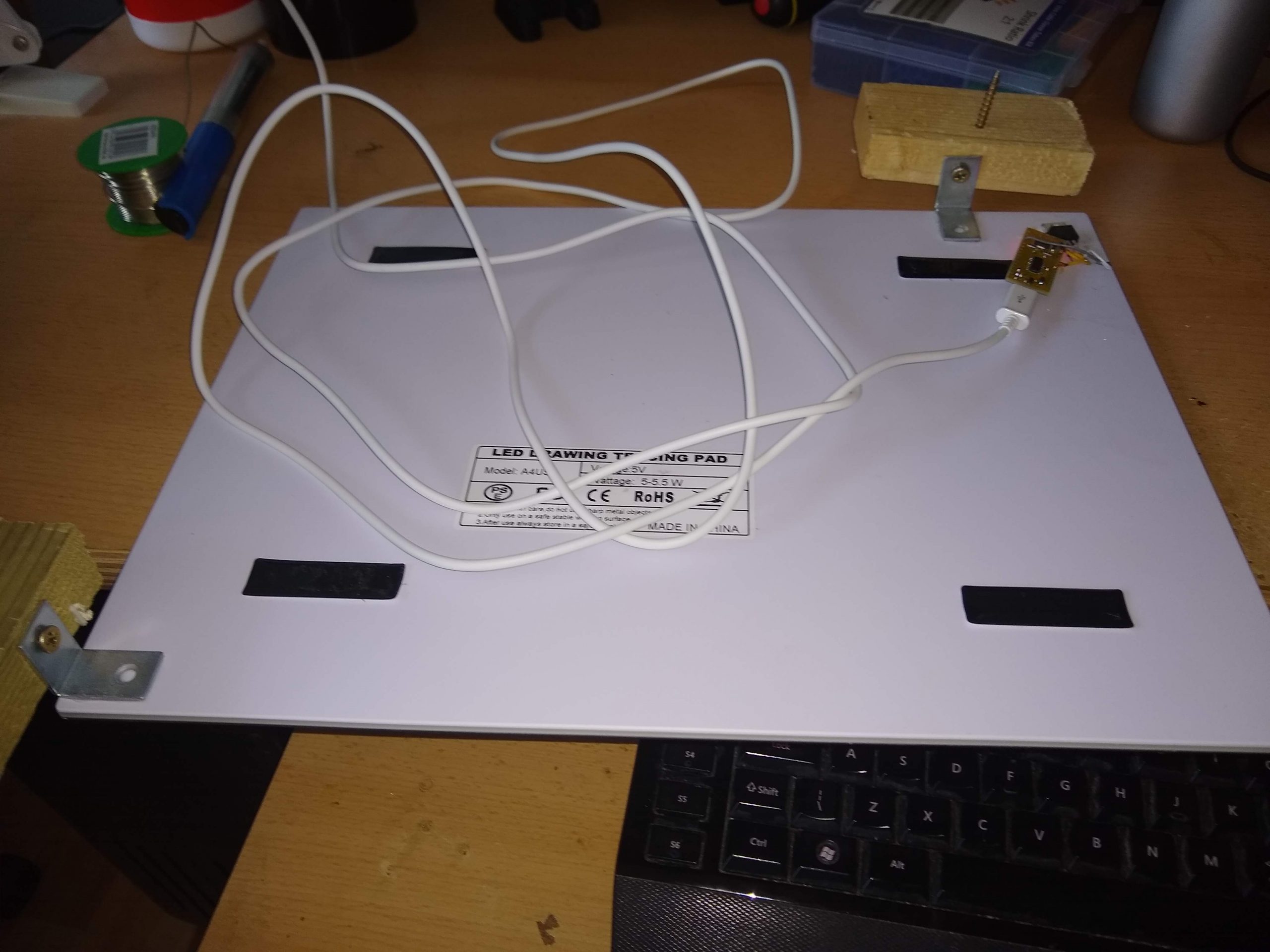
Next secure the Nano and MOSFET to the back of the tracing panel; I just cut a length of strong Duck Tape and used it to stick the parts down, ensuring I didn’t create any short-circuits in the wiring. In order to mount the panel in my observatory, I used superglue to fix a couple of small metal brackets to the rear of the panel, and then screwed a couple of wooden blocks to the brackets.
The panel was then secured to my observatory wall using a couple more screws through the wooden blocks. The panel is positioned far enough away from the scope and mount that nothing can collide when the scope is in use, but sufficiently close that the scope’s entire field of view is filled by the panel when pointed at it. I created a custom park position in EQMOD to ensure that the scope is centered on the panel and square with it when parked.

You will have to determine the best location and means of mounting the panel; my observatory is (deliberately) small so it was easy to find a suitable way to get the panel to fill the scope’s field of view. If your walls are further away, you may have to mount everything on a fixed or movable framework of some sort.
Using the Panel

The flat panel can be set up in any imaging software that supports Alnitak flat panels; just select Alnitak (and FlatMan if a model is required) in your software’s configuration screen. You will need to select the COM port to which the panel is connected, either the COM port used in the Arduino IDE, or perhaps a different one if you have a separate observatory computer. Generally speaking no drivers need to be installed for Alnitak panels. The only caveat is that if your Arduino board required serial drivers to be installed as part of the setup process, these need to be installed on your observatory PC too, but this isn’t usually necessary.
N.B. Bear in mind that different sketches may be needed for Sequence Generator Pro vs. N.I.N.A. as described in the programming section above.
At the full (255) brightness level, this panel is bright enough to expose to 25,000 ADU in a few hundredths of a second for LRGB filters, and about half a second for narrow-band filters. I have found that with such short exposures, banding can appear in the LRGB flat frames (dark and light strips). In my case I suspect the cause is flicker/interference caused by the PWM circuit or possibly the camera/mains frequency, but this can also happen with cameras that have a mechanical shutter. Using a much lower brightness (around 10) pushes the required exposure time up to 0.1 to 0.3 seconds. This gets rid of the banding.
For my ASI 1600MM-C (older non-Pro version), exposures of over a two seconds (USB 3) or five seconds (USB2) switch to a different readout mode which can create gradients as the image continues to expose whilst being read out. You’ll have to experiment for your particular setup – you can dim the panel significantly using the brightness settings, and if necessary you can always stick one or more sheets of white paper over the panel to dim it further if you have banding or mechanical shutter issues to contend with.
Very nice! You have inspired me to make one. Any reason you chose a LED panel instead of an EL one?
I choose an LED panel on grounds of brightness, cost and simplicity. EL panels are relatively dim and thus require longer flat exposures, especially for narrowband filters. This is problematic for the ZWO ASI1600MM-C (original version) as the readout mode changes for exposures greater than about a second. The frame continues to expose as it is being read out, and this creates a gradient as the last rows to be read out have a longer exposures than the first rows. This isn’t a major issue for normal (light) frames due to the small amount of illumination, but creates artefacts for flats with a much brighter light source. Also I wanted a panel I could wall mount rather than having to place on the end of the scope each time, and larger EL panels are more expensive. Finally EL panels need a high-voltage driver. I’m sure it is possible to use an Arduino and additional circuitry to control and dim them, but the LED panels are much simpler for those of us with limited electronics skills.
I ended up making one just like yours. I recently switched to NINA and it could not be controlled by NINA because the response commands were typoed/incorrect. I fixed it and put the updated code here:
https://github.com/red-man/Alnitak-Lightbox-Clone
Thanks Chris, most helpful. I have updated the post accordingly.
Thanks so much for this great article
Having trouble finding a suitable light box on amazon uk in September 2020
Can’t see the criteria listed in descriptions on amazon uk.
Could anyone recommend one pls?
Thanks
It’s a shame there’s no links to suitable panels.
As noted in the post, they come and go quickly so it’s impossible to make a specific recommendation.
Any idea how an EL panel could be controlled? I have a Gerd Newman panel that I’d love to control remotely but it uses a 12v transformer.
As far as I know EL panels like this use a driver which takes in 12V and puts out the much higher voltage required to drive the panel. I’m not sure if they are dimmable by varying the voltage or using PWM similar to what I have done with LEDs here. The simplest option would probably be to turn the 12V supply to the EL driver, which could be done using a relay or a Mosfet. You’d need to account for the fact that the driver takes 12V and the microcontroller 5V or 3.3V, which is a bit more complicated than the LED setup where everything is running at the 5V USB voltage. I’d imagine there are any number of designs online that could be adapted if you search for them.
I just finished modifying my ~$40 USD Cricut LED panel with your fantastic instructions above for use with NINA, and it works like a charm! I went from an annoying manual on/off button and 3 levels of illumination to being fully controlled by NINA and 255 levels. Very happy with the result and thank you for posting your clear and precise instructions!
Thanks, I’m glad you found it useful.
I almost have my light panel completed. The LED Panel I used had 2 sets of leads for the LEDs. So, I just tied them together and the panel seems to work that way.
However, now I’m having a problem getting the panel to display anything other than full brightness. Here’s a transcript of a Serial Monitor session:
Command: >S000
Reply: * S19000
>B255
*B19255
>L000
*L19000 (LED turns on to brightest? setting)
>B127
*B19127
>L000
Then, the LED blinks once, turns off and a backwards question mark comes up.
Any ideas? Thanks.
Here’s the Arduino I bought:
https://www.amazon.com/HiLetgo-ATmega328P-Controller-Development-Unsoldered/dp/B01DLIJQA2/ref=sr_1_2_sspa?dchild=1&keywords=hiletgo+nano+v3.0+atmega328p+board&qid=1627932183&sr=8-2-spons&psc=1&spLa=ZW5jcnlwdGVkUXVhbGlmaWVyPUEyNzRNVFMzRzFOTVhZJmVuY3J5cHRlZElkPUEwMjMyNzcxMlROQVZSTjlTUjZPRCZlbmNyeXB0ZWRBZElkPUEwMDQ0MjM3MjNGVjRKWThEMlYwSyZ3aWRnZXROYW1lPXNwX2F0ZiZhY3Rpb249Y2xpY2tSZWRpcmVjdCZkb05vdExvZ0NsaWNrPXRydWU=
Sorry it’s really hard to know what the issue is. It looks like the sketch is responding correctly to the commands up until the last L000. Things to try:
– Check that you have selected the correct board/processor in the Arduino iDE before compiling/uploading the sketch.
– Select a low baud rate in the serial monitor to rule out any communications problems.
– Make sure you have wired the Mosfet correctly and there is enough current from the supply to power the LEDs. Sounds like there is because the LEDs are coming on in the first place.
– Check the power supply and connection to the Arduino, a drop in voltage might cause it to crash.
Beyond that, the sketch isn’t very forgiving of invalid input and will typically hang if it gets something it wasn’t expecting. I can only suggest you put in some print commands to send text to the serial monitor in various places to see if you can figure out where it is crashing and why.
Thanks! I’ll give those a try.
Good news! Making some progress on troubleshooting. I bought another version of what I thought was the same Nano ATmega328p except with dual in-line pins so I could mount it in a breadboard and demo it. Found out it did have one difference: it required the old boot loader. I got the new one programmed and proved it worked with a utility LED and that the voltage varied appropriately. So, I bypassed my original Nano/MOSFET circuit and connected directly to the LED lights in the panel. And, I was able to command different brightnesses with this setup! However, the voltage doesn’t vary as much between B001 and B255 as I think it should. I wonder if the weird 2 separate leads for this panel puts too much load on the power of this circuit? However, I think I might have found an A3 panel that may be more similar to yours and I’ve ordered it to give it a try. Here’s the link:
https://www.amazon.com/gp/product/B018XATVM6/ref=ppx_yo_dt_b_asin_title_o04_s00?ie=UTF8&psc=1
I’ll let you know how it goes!
Thanks,
Ted
Thanks Ted. It wasn’t clear from your reply whether the new Nano was connected directly from the PWM to the panel LEDs without a MOSFET? If so I wouldn’t expect the current to be sufficient to run the panels at full brightness if at all, that’s the purpose of the MOSFET part of the circuit. Anyway glad you’re getting somewhere.
Oh, sorry for the confusion. I retained the MOSFET; I just replaced the initial Nano with my “newer” one that requires the Old Bootloader. That setup works pretty good; but I’m still puzzled why the voltage doesn’t vary from 0 to 5 volts. With this panel, a brightness setting of 001 outputs a voltage of 2.5v on pin 6. A brightness setting of 255 outputs a voltage of 3.35v and 127 outputs 2.75v. Good news is there is still a lot of range in the brightness. The shutter speed required to obtain an ADU of 27100 at B001 is 0.53s. At B255, the shutter speed is 0.00435. 0.53/0.00435 is a dynamic range of 121! This stock panel had the ability to continuously adjust its brightness. But, the ratio of the brightest setting to the dimmest setting was 11 before. So, this mod extends the dynamic range from 11 to 121!
Since this Nano that works properly has breadboard pins, I’ve ordered a small breadboard to mount it in and a box to cover the additional circuitry. Looking forward to having a controllable Flat Light for SG Pro!
Thanks,
Ted
Great article, clear instructions.
I have just spent a grand total of one hour following your instructions. I now have a flat panel working with NINA. What more can I say.
Thanks very much!
Aaron
Great Project! Afraid I can not get to work. I have tried 3 different Nanos and MOSFET’s so far.
The LED is on at full.. Have checked and checked again but no joy. Have attached LED Panel and also a single 5v LED.
Any idea where I should start!
I am getting 4.18v on the 5v pin on the board and ground.
Also tried both sketches
SUCCESS! Had a problem with a faulty USB Cable but all good and working fine now with NINA. Thanks so much for sharing this project. Dark Skies! Trev
Is there a code for using this with an INDI driver? It would be cool if it can be controlled via an RPi on the scope itself.
If there is an INDI driver for the Alnitak Flip-Flat or Flatman flat panels it should work with this just fine since it uses the same protocol.
Thanks so much for your work and sharing. I found a used MOSFET FQP50N06 in an old amp of mine. I hooked this up to test but I think the voltages may be an issue. The panel responds to the commands with a few exceptions and observations. It will not go to full brightness and will not turn off. I have ordered the MOSFET you recommended but I was wondering if you could tell me why this one causes the issues I’m seeing if it in fact is.
Sorry, I really couldn’t say anything about that specific device. I’ve only tested using the recommended one.
Thank you so much. I was looking for ways to control the LED panel and modifying so that I can auto switch it on and off at max and then let NINA compute the exposure. However your suggestions motivated me to roll up my sleeve and clean up my soldering iron. Once I got the components within an hour I got it up and running.
I was facing the same problem that Ted Stokes mentioned, namely there were two LED circuits and I had to join them together in parallel, also the 5V pin on the Nano, was not able to drive the LED panel and it caused the LED panel to light up and then go off, this is because Nano would reset on power drain, at any value other than 255, solved that by using a different power source for LED panel but retained everything else in your suggestions. Works great !!